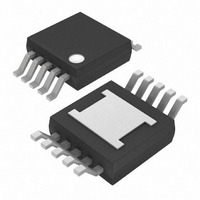
MAX7306AUB+ Maxim Integrated Products, MAX7306AUB+ Datasheet - Page 11

MAX7306AUB+
Manufacturer Part Number
MAX7306AUB+
Description
IC LED DRIVER LINEAR 10-UMAX
Manufacturer
Maxim Integrated Products
Type
Linear (I²C Interface)r
Datasheet
1.MAX7306AUB.pdf
(23 pages)
Specifications of MAX7306AUB+
Topology
PWM
Number Of Outputs
4
Internal Driver
Yes
Type - Primary
Backlight, LED Blinker
Type - Secondary
White LED
Frequency
1MHz
Voltage - Supply
1.62 V ~ 3.6 V
Mounting Type
Surface Mount
Package / Case
10-MSOP Exposed Pad, 10-HMSOP, 10-eMSOP
Operating Temperature
-40°C ~ 125°C
Current - Output / Channel
25mA
Internal Switch(s)
No
Lead Free Status / RoHS Status
Lead free / RoHS Compliant
Voltage - Output
-
Efficiency
-
Lead Free Status / Rohs Status
Details
Figure 1. Input Port Structure
Table 7. Port I/O Registers (I/O Port Set as an Output, Registers 0x01 to 0x04)
SMBus/I
REGISTER BIT
D7
D6
D5
D4
D3
D2
D1
D0
PORT_[0]
(PORTIN)
______________________________________________________________________________________
PWM/Blink Enable
Output Port Set to
Duty Cycle Bit 4
Duty Cycle Bit 3
Duty Cycle Bit 2
Duty Cycle Bit 1
Duty Cycle Bit 0
DESCRIPTION
2
Port I/O Set Bit
or Open-Drain
(DEBOUNCE)
PORT_[2]
Push-Pull
C Interfaced 4-Port, Level-Translating
0
1
INT
TRANSITION
DETECTION
VALUE
INT2
INT4
0
0
1
0
1
0
1
0
1
0
1
0
1
0
1
INTERRUPT
LOGIC
INT
Sets the I/O port as an output.
Sets the output type to open-drain.
Sets the output type to push-pull.
Sets the output to PWM mode.
Sets the output to blink mode.
MSB of the 5-bit duty cycle setting. See the PWM and Blink Timing section.
MSB of the 5-bit duty cycle setting. See the PWM and Blink Timing section.
Bit 3 of the 5-bit duty cycle setting. See the PWM and Blink Timing section.
Bit 3 of the 5-bit duty cycle setting. See the PWM and Blink Timing section.
Bit 2 of the 5-bit duty cycle setting. See the PWM and Blink Timing section.
Bit 2 of the 5-bit duty cycle setting. See the PWM and Blink Timing section.
Bit 1 of the 5-bit duty cycle setting. See the PWM and Blink Timing section.
Bit 1 of the 5-bit duty cycle setting. See the PWM and Blink Timing section.
LSB of the 5-bit duty cycle setting. See the PWM and Blink Timing section.
LSB of the 5-bit duty cycle setting. See the PWM and Blink Timing section.
TRANSITION
DETECTION
GPIOs and LED Drivers
PORT_ [5]
INTERRUPT
ENABLE
DEBOUNCE LOGIC
(THRESHOLD
PORT_[6]
SELECT)
FUNCTION
V
DD
1
0
V
LA
MAX7307 ONLY
I/O
11


