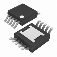
MAX7306AUB+ Maxim Integrated Products, MAX7306AUB+ Datasheet - Page 7

MAX7306AUB+
Manufacturer Part Number
MAX7306AUB+
Description
IC LED DRIVER LINEAR 10-UMAX
Manufacturer
Maxim Integrated Products
Type
Linear (I²C Interface)r
Datasheet
1.MAX7306AUB.pdf
(23 pages)
Specifications of MAX7306AUB+
Topology
PWM
Number Of Outputs
4
Internal Driver
Yes
Type - Primary
Backlight, LED Blinker
Type - Secondary
White LED
Frequency
1MHz
Voltage - Supply
1.62 V ~ 3.6 V
Mounting Type
Surface Mount
Package / Case
10-MSOP Exposed Pad, 10-HMSOP, 10-eMSOP
Operating Temperature
-40°C ~ 125°C
Current - Output / Channel
25mA
Internal Switch(s)
No
Lead Free Status / RoHS Status
Lead free / RoHS Compliant
Voltage - Output
-
Efficiency
-
Lead Free Status / Rohs Status
Details
The MAX7306/MAX7307 4-port, general-purpose port
expanders operate from a 1.62V to 3.6V power supply.
Ports P2 through P4 can be configured as inputs, push-
pull outputs, and open-drain outputs. Port P1 can be
configured as an input and an open-drain output; P1
can also be configured to function as an (INT) output.
Each port configured as an open-drain or push-pull
output can sink up to 25mA. Push-pull outputs also
have a 10mA source drive capability. The MAX7306/
MAX7307 are rated to sink a total of 100mA into any
combination of the output ports. Output ports have
PWM and blink capabilities, as well as logic drive.
SMBus/I
MAX7306 ONLY
SDA
SCL
_______________________________________________________________________________________
2
Detailed Description
C Interfaced 4-Port, Level-Translating
MAX7306/
MAX7307
REGISTER
BANK
I 2 C
CONTROL
OUTPUT
LOGIC
V
I/O
DD
On power-up, the MAX7307 default configuration has
all ports configured as input ports with logic levels ref-
erenced to V
has all ports configured as input ports with logic levels
referenced to V
status flag resets and stays high (see Tables 1 and 2).
The device configuration registers set up the interrupt
function, serial-interface bus timeout, PWM/blink, oscil-
lator options, global blink period, and reset options
(see Tables 3 and 4).
GPIOs and LED Drivers
LA
Device Configuration Registers
. The MAX7306 default configuration
INPUT
LOGIC
DD
V
I/O
LA
. The transition detection interrupt
MAX7307 ONLY
Block Diagram
Initial Power-Up
P1–P4
7


