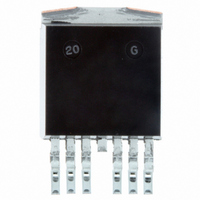
BUK218-50DC,118 NXP Semiconductors, BUK218-50DC,118 Datasheet - Page 3

BUK218-50DC,118
Manufacturer Part Number
BUK218-50DC,118
Description
TOPFET DUAL SWITCH D2PAK
Manufacturer
NXP Semiconductors
Datasheet
1.BUK218-50DC118.pdf
(9 pages)
Specifications of BUK218-50DC,118
Configuration
High-Side
Delay Time
30µs
Current - Peak
8A
Voltage - Supply
6 V ~ 35 V
Operating Temperature
-40°C ~ 150°C
Mounting Type
Surface Mount
Package / Case
D²Pak, TO-263 (6 leads + tab)
Lead Free Status / RoHS Status
Lead free / RoHS Compliant
Number Of Outputs
-
Input Type
-
Number Of Configurations
-
High Side Voltage - Max (bootstrap)
-
Other names
934056877118
BUK218-50DC /T3
BUK218-50DC /T3
BUK218-50DC /T3
BUK218-50DC /T3
Philips Semiconductors
THERMAL CHARACTERISTIC
STATIC CHARACTERISTICS
Limits are at -40˚C
1 Of the output Power MOS transistors.
2 For a high side switch, the load pin voltage goes negative with respect to ground during the turn-off of an inductive load. This negative voltage
3 On-state resistance is increased if the supply voltage is less than 7 V.
4 This is the continuous current drawn from the battery when both inputs are low and includes leakage currents to the loads.
5 Per channel but with both channels conducting. Defined as in ISO 10483-1.
6 Equivalent of the parallel connected resistors for both channels.
7 The supply and input voltage for the R
October 2001
TOPFET dual high side switch
SYMBOL PARAMETER
R
SYMBOL PARAMETER
V
V
V
V
I
I
I
I
R
R
R
B
L
G
L
BG
BL
GL
BG
th j-mb
G
ON
ON
is clamped by the device.
Thermal resistance
Junction to mounting base
Clamping voltages
Battery to ground
Battery to load per channel
Ground to load
Supply voltage
Operating range
Currents
Total quiescent current
Off-state load current per
channel
Operating current
Nominal load current
Effective internal ground
resistance
Resistances per channel
On-state resistance
On-state resistance
T
mb
6
150˚C and typicals at T
2
3
ON
1
5
tests are continuous. The specified pulse duration t
4
CONDITIONS
CONDITIONS
I
I
I
I
9 V
V
V
one channel on
both channels on
V
I
G
L
L
L
G
9 to 35 V
per channel
both channels
battery to ground
-
LG
BL
BL
= I
= 10 mA
= 10 A; t
= 1 mA
= -200 mA; t
5.5 V
mb
V
= V
= 0.5 V; T
= 0 V
G
BG
V
= 25 ˚C unless otherwise stated
= 1 mA
BG
BG
p
3
35 V
= 300 s
10 A
mb
5 A
p
I
L
= 300 s
= 85˚C
300 s
300 s
t
p
T
T
7
mb
mb
= 25˚C
= 25˚C
p
150˚C
150˚C
refers only to the applied load current.
25˚C
25˚C
T
j
MIN.
MIN.
5.5
45
50
18
20
40
8
-
-
-
-
-
-
-
-
-
-
-
-
TYP.
TYP.
100
2.4
1.2
0.1
0.1
1.8
3.6
55
55
23
25
75
30
60
50
BUK218-50DC
-
-
-
-
Product specification
MAX.
MAX.
100
120
1.5
65
65
28
30
35
20
10
40
80
60
3
1
1
3
6
-
Rev 2.010
UNIT
UNIT
K/W
K/W
m
m
m
m
mA
mA
V
V
V
V
V
A
A
A
A
A


