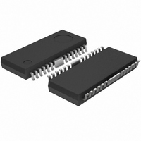
BD6232FP-E2 Rohm Semiconductor, BD6232FP-E2 Datasheet - Page 10

BD6232FP-E2
Manufacturer Part Number
BD6232FP-E2
Description
IC H-BRIDGE DRIVER 1CH 2A HSOP25
Manufacturer
Rohm Semiconductor
Type
Half Bridge Driverr
Specifications of BD6232FP-E2
Applications
DC Motor Driver
Number Of Outputs
1
Current - Output
2A
Voltage - Supply
6 V ~ 32 V
Operating Temperature
-40°C ~ 85°C
Mounting Type
Surface Mount
Package / Case
25-HSOP
No. Of Outputs
1
Output Current
2A
Supply Voltage Range
6V To 32V
Driver Case Style
HSOP
No. Of Pins
25
Operating Temperature Range
-40°C To +85°C
Svhc
No SVHC (18-Jun-2010)
Package /
RoHS Compliant
Product
H-Bridge Drivers
Supply Voltage (max)
36 V
Supply Voltage (min)
6 V
Supply Current
1.3 mA
Maximum Power Dissipation
1.45 W
Maximum Operating Temperature
+ 85 C
Mounting Style
SMD/SMT
Bridge Type
H-bridge
Minimum Operating Temperature
- 40 C
Number Of Drivers
1
Operating Supply Voltage
6 V to 32 V
Motor Type
H-Bridge
Rohs Compliant
Yes
Base Number
6232
Lead Free Status / RoHS Status
Lead free / RoHS Compliant
Voltage - Load
-
Lead Free Status / Rohs Status
Lead free / RoHS Compliant
Other names
BD6232FP-E2TR
Available stocks
Company
Part Number
Manufacturer
Quantity
Price
Company:
Part Number:
BD6232FP-E2
Manufacturer:
ROHM Semiconductor
Quantity:
592
○
BD6230, BD6231, BD6232, BD6235, BD6236, BD6237
c
www.rohm.com
2009 ROHM Co., Ltd. All rights reserved.
e) f) PWM control mode A
g) h) PWM control mode B
The rotational speed of the motor can be controlled by the switching duty when the PWM signal is input to the FIN
pin or the RIN pin. In this mode, the high side output is fixed and the low side output does the switching,
corresponding to the input signal. The switching operates by the output state toggling between "L" and "Hi-Z".
The PWM frequency can be input in the range between 20kHz and 100kHz. Note that control may not be attained
by switching on duty at frequencies lower than 20kHz, since the operation functions via the stand-by mode. Also,
circuit operation may not respond correctly when the input signal is higher than 100kHz. To operate in this mode,
connect the VREF pin with VCC pin. In addition, establish a current path for the recovery current from the motor, by
connecting a bypass capacitor (10µF or more is recommended) between VCC and ground.
The rotational speed of the motor can be controlled by the switching duty when the PWM signal is input to the FIN
pin or the RIN pin. In this mode, the low side output is fixed and the high side output does the switching,
corresponding to the input signal. The switching operates by the output state toggling between "L" and "H".
The PWM frequency can be input in the range between 20kHz and 100kHz. Also, circuit operation may not respond
correctly when the input signal is higher than 100kHz. To operate in this mode, connect the VREF pin with VCC pin.
In addition, establish a current path for the recovery current from the motor, by connecting a bypass capacitor (10µF
or more is recommended) between VCC and ground.
OUT1
OUT2
OUT1
OUT2
RIN
RIN
FIN
FIN
OFF
OFF
ON
ON
Control input : H
Control input : H
Fig.40 PWM control mode B operation (output stage)
Fig.38 PWM control mode A operation (output stage)
Fig.41 PWM control mode B operation (timing chart)
Fig.39 PWM control mode A operation (timing chart)
M
M
OFF
ON
OFF
ON
10/16
OFF
OFF
ON
ON
Control input : L
Control input : L
M
M
OFF
OFF
OFF
ON
2009.08 - Rev.C
Technical Note


