BD6232FP-E2 Rohm Semiconductor, BD6232FP-E2 Datasheet - Page 13
BD6232FP-E2
Manufacturer Part Number
BD6232FP-E2
Description
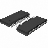
IC H-BRIDGE DRIVER 1CH 2A HSOP25
Manufacturer
Rohm Semiconductor
Type
Half Bridge Driverr
Specifications of BD6232FP-E2
Applications
DC Motor Driver
Number Of Outputs
1
Current - Output
2A
Voltage - Supply
6 V ~ 32 V
Operating Temperature
-40°C ~ 85°C
Mounting Type
Surface Mount
Package / Case
25-HSOP
No. Of Outputs
1
Output Current
2A
Supply Voltage Range
6V To 32V
Driver Case Style
HSOP
No. Of Pins
25
Operating Temperature Range
-40°C To +85°C
Svhc
No SVHC (18-Jun-2010)
Package /
RoHS Compliant
Product
H-Bridge Drivers
Supply Voltage (max)
36 V
Supply Voltage (min)
6 V
Supply Current
1.3 mA
Maximum Power Dissipation
1.45 W
Maximum Operating Temperature
+ 85 C
Mounting Style
SMD/SMT
Bridge Type
H-bridge
Minimum Operating Temperature
- 40 C
Number Of Drivers
1
Operating Supply Voltage
6 V to 32 V
Motor Type
H-Bridge
Rohs Compliant
Yes
Base Number
6232
Lead Free Status / RoHS Status
Lead free / RoHS Compliant
Voltage - Load
-
Lead Free Status / Rohs Status
Lead free / RoHS Compliant
Other names
BD6232FP-E2TR
Available stocks
Company
Part Number
Manufacturer
Quantity
Price
Company:

Part Number:
BD6232FP-E2
Manufacturer:
ROHM Semiconductor
Quantity:
592


Notes for use
○
BD6230, BD6231, BD6232, BD6235, BD6236, BD6237
c
www.rohm.com
2009 ROHM Co., Ltd. All rights reserved.
10) Capacitor between output and GND
1) Absolute maximum ratings
2) Connecting the power supply connector backward
3) Power supply lines
4) Electrical potential at GND
5) Thermal design
6) Inter-pin shorts and mounting errors
7) Operation in strong electromagnetic fields
8) ASO - Area of Safety Operation
9) Built-in thermal shutdown (TSD) circuit
Devices may be destroyed when supply voltage or operating temperature exceeds the absolute maximum rating.
Because the cause of this damage cannot be identified as, for example, a short circuit or an open circuit, it is important
to consider circuit protection measures – such as adding fuses – if any value in excess of absolute maximum ratings is
to be implemented.
Connecting the power supply in reverse polarity can damage the IC. Take precautions against reverse polarity when
connecting the power supply lines, such as adding an external direction diode.
Return current generated by the motor’s Back-EMF requires countermeasures, such as providing a return current path
by inserting capacitors across the power supply and GND (10µF, ceramic capacitor is recommended). In this case, it is
important to conclusively confirm that none of the negative effects sometimes seen with electrolytic capacitors –
including a capacitance drop at low temperatures - occurs. Also, the connected power supply must have sufficient
current absorbing capability. Otherwise, the regenerated current will increase voltage on the power supply line, which
may in turn cause problems with the product, including peripheral circuits exceeding the absolute maximum rating. To
help protect against damage or degradation, physical safety measures should be taken, such as providing a voltage
clamping diode across the power supply and GND.
Keep the GND terminal potential to the minimum potential under any operating condition. In addition, check to
determine whether there is any terminal that provides voltage below GND, including the voltage during transient
phenomena. When both a small signal GND and high current GND are present, single-point grounding (at the set’s
reference point) is recommended, in order to separate the small signal and high current GND, and to ensure that
voltage changes due to the wiring resistance and high current do not affect the voltage at the small signal GND. In the
same way, care must be taken to avoid changes in the GND wire pattern in any external connected component.
Use a thermal design that allows for a sufficient margin in light of the power dissipation (Pd) under actual operating
conditions.
Use caution when positioning the IC for mounting on printed circuit boards. The IC may be damaged if there is any
connection error, or if pins are shorted together.
Using this product in strong electromagnetic fields may cause IC malfunctions. Use extreme caution with
electromagnetic fields.
When using the IC, set the output transistor so that it does not exceed absolute maximum ratings or ASO.
The TSD circuit is designed only to shut the IC off to prevent thermal runaway. It is not designed to protect the IC or
guarantee its operation in the presence of extreme heat. Do not continue to use the IC after the TSD circuit is activated,
and do not operate the IC in an environment where activation of the circuit is assumed.
In the event a large capacitor is connected between the output and GND, if VCC and VIN are short-circuited with 0V or
GND for any reason, the current charged in the capacitor flows into the output and may destroy the IC. Use a capacitor
smaller than 1μF between output and GND.
13/16
2009.08 - Rev.C
Technical Note
Related parts for BD6232FP-E2
Image
Part Number
Description
Manufacturer
Datasheet
Request
R

Part Number:
Description:
Manufacturer:
Rohm Semiconductor
Datasheet:
Part Number:
Description:
Manufacturer:
Rohm Semiconductor
Datasheet:
Part Number:
Description:
Manufacturer:
Rohm Semiconductor
Datasheet:
Part Number:
Description:
Manufacturer:
Rohm Semiconductor
Datasheet:
Part Number:
Description:
Manufacturer:
Rohm Semiconductor
Datasheet:
Part Number:
Description:
Manufacturer:
Rohm Semiconductor
Datasheet:
Part Number:
Description:
Manufacturer:
Rohm Semiconductor
Datasheet:
Part Number:
Description:
Manufacturer:
Rohm Semiconductor
Datasheet:
Part Number:
Description:
Manufacturer:
Rohm Semiconductor
Datasheet:
Part Number:
Description:
Manufacturer:
Rohm Semiconductor
Datasheet:
Part Number:
Description:
Manufacturer:
Rohm Semiconductor
Datasheet:
Part Number:
Description:
Manufacturer:
Rohm Semiconductor
Datasheet:

Part Number:
Description:
DIODE SWITCH 80V 25MA SMD5 TR
Manufacturer:
Rohm Semiconductor
Datasheet: