LMD18201T/NOPB National Semiconductor, LMD18201T/NOPB Datasheet - Page 8
LMD18201T/NOPB
Manufacturer Part Number
LMD18201T/NOPB
Description
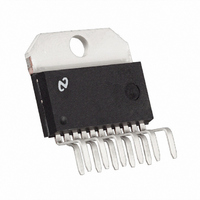
IC H BRIDGE 3A 55V TO220-11
Manufacturer
National Semiconductor
Specifications of LMD18201T/NOPB
Applications
DC Motor Driver, Stepper Motor Driver, H Bridge
Number Of Outputs
1
Current - Output
3A
Voltage - Supply
12 V ~ 55 V
Operating Temperature
-40°C ~ 125°C
Mounting Type
Through Hole
Package / Case
TO-220-11 (Bent and Staggered Leads)
Lead Free Status / RoHS Status
Lead free / RoHS Compliant
Voltage - Load
-
Lead Free Status / Rohs Status
RoHS Compliant part
Electrostatic Device
Other names
*LMD18201T
*LMD18201T/NOPB
LMD18201T
*LMD18201T/NOPB
LMD18201T


www.national.com
Application Information
reverse recovery current of 1A when tested with a full 3A of
forward current through the diode. For the sinking devices
the recovery time is typically 100 ns with 4A of reverse
current under the same conditions.
Typical Applications
BASIC MOTOR DRIVER
The LMD18201 can directly interface to any Sign/Magnitude
PWM controller. The LM629 is a motion control processor
that outputs a Sign/Magnitude PWM signal to coordinate
either positional or velocity control of DC motors. The
LMD18201 provides fully protected motor driver stage.
CURRENT SENSING
In many motor control applications it is desirable to sense
and control the current through the motor. For these types of
applications a companion product, the LMD18200, is also
available. The LMD18200 is identical to the LMD18201 but
has current sensing transistors that output a current directly
proportional to the current conducted by the two upper
DMOS power devices to a separate current sense pin. This
technique does not require a low valued, power sense resis-
tor and does not subtract from the available voltage drive to
the motor.
To sense the bridge current through the LMD18201 requires
the addition of a small sense resistor between the power
ground/sense pin (Pin 7) and the actual circuit ground (see
Figure 8). This resistor should have a value of 0.1Ω or less to
(Continued)
FIGURE 7. Basic Motor Driver
8
stay within the allowable voltage compliance of the sense
pin, particularly at higher operating current levels. The volt-
age between power ground/sense (Pin 7) and the signal
ground (Pin 8) must stay within the range of −1V to +0.5V.
Internally there is approximately 25Ω between pins 7 and 8
and this resistance will slightly reduce the value of the ex-
ternal sense resistor. Approximately 70% of the quiescent
supply current (10 mA) flows out of pin 7. This will cause a
slight offset to the voltage across the sense resistor when
the bridge is not conducting. During reverse recovery of the
internal protection diodes the voltage compliance between
pins 7 and 8 may be exceeded. The duration of these spikes
however are only approximately 100 ns and do not have
enough time or energy to disrupt the operation of the
LMD18201.
01079310
Related parts for LMD18201T/NOPB
Image
Part Number
Description
Manufacturer
Datasheet
Request
R

Part Number:
Description:
IC, MOTOR CTRL, HALF BRIDGE 3A TO-220-11
Manufacturer:
National Semiconductor
Datasheet:

Part Number:
Description:
National Semiconductor [8-Bit D/A Converter]
Manufacturer:
National Semiconductor
Datasheet:
Part Number:
Description:
National Semiconductor [Media Coprocessor]
Manufacturer:
National Semiconductor
Datasheet:
Part Number:
Description:
Digitally Controlled Tone and Volume Circuit with Stereo Audio Power Amplifier, Microphone Preamp Stage and National 3D Sound
Manufacturer:
National Semiconductor
Datasheet:
Part Number:
Description:
Digitally Controlled Tone and Volume Circuit with Stereo Audio Power Amplifier, Microphone Preamp Stage and National 3D Sound
Manufacturer:
National Semiconductor
Datasheet:
Part Number:
Description:
AC97 Rev 2 Codec with Sample Rate Conversion and National 3D Sound
Manufacturer:
National Semiconductor
Part Number:
Description:
Manufacturer:
National Semiconductor
Datasheet:
Part Number:
Description:
Manufacturer:
National Semiconductor
Datasheet:
Part Number:
Description:
General Purpose, Low Voltage, Low Power, Rail-to-Rail Output Operational Amplifiers
Manufacturer:
National Semiconductor
Datasheet:
Part Number:
Description:
8-bit 20 MSPS flash A/D converter.
Manufacturer:
National Semiconductor
Datasheet:
Part Number:
Description:
Low Noise Quad Operational Amplifier
Manufacturer:
National Semiconductor
Datasheet:
Part Number:
Description:
Quad Differential Line Receivers
Manufacturer:
National Semiconductor
Datasheet:
Part Number:
Description:
Quad High Speed Trapezoidal? Bus Transceiver
Manufacturer:
National Semiconductor
Datasheet:
Part Number:
Description:
Dual Line Receiver
Manufacturer:
National Semiconductor
Datasheet: