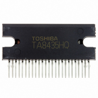
TA8435HQ(5) Toshiba, TA8435HQ(5) Datasheet

TA8435HQ(5)
Specifications of TA8435HQ(5)
Related parts for TA8435HQ(5)
TA8435HQ(5) Summary of contents
Page 1
... TOSHIBA BIPOLAR LINEAR INTEGRATED CIRCUIT SILICON MONOLITHIC PWM CHOPPER-TYPE BIPOLAR STEPPING MOTOR DRIVER. The TA8435H/ PWM chopper-type sinusoidal micro-step bipolar stepping motor driver. Sinusoidal micro-step operation is achieved using only a clock signal input by means of built-in hardware. FEATURES Single-chip bipolar sinusoidal micro-step stepping motor driver Output current ...
Page 2
BLOCK DIAGRAM Non-connection 2 TA8435H/HQ 2006-3-2 ...
Page 3
PIN CONNECTION (top view) Note: NC: No connection 3 TA8435H/HQ 2006-3-2 ...
Page 4
PIN FUNCTION PIN No SYMBOL RESET 3 ENABLE 4 OSC CCW 6 CK2 7 CK1 REF ...
Page 5
OUTPUT CIRCUIT INPUT CIRCUIT CK1, CK2 CCW, M1, M2, REF IN: Terminals RESET , ENABLE : Terminals Equipped with 100 kΩ of pull-up resistance. 5 TA8435H/HQ OSC: Terminal 2006-3-2 ...
Page 6
OSCILLATOR FREQUENCY CALCULATION The sawtooth oscillator (OSC) circuit consists of Q less than the voltage of 2 charging through R1. Q and Q are turned on when equal ...
Page 7
ENABLE AND RESET FUNCTION AND MO SIGNAL Figure 1: 1-2 phase drive mode (M1: H, M2: L) The ENABLE signal at High level disables only the output signals. Internal logic functions proceed in accordance with input clock signals and without ...
Page 8
FUNCTION INPUT CK1 CK2 CW / CCW RESET ...
Page 9
W1-2-PHASE EXCITATION (M1 MODE) 9 TA8435H/HQ 2006-3-2 ...
Page 10
EXCITATION (M1 MODE) 10 TA8435H/HQ 2006-3-2 ...
Page 11
ABSOLUTE MAXIMUM RATINGS CHARACTERISTIC Supply Voltage Output Voltage PEAK Output Current AVE MO Output Current Input Voltage Power Dissipation Operating Temperature Storage Temperature Feed Back Voltage Note 1: No heat sink Note 85°C RECOMMENDED OPERATING CONDITIONS CHARACTERISTIC ...
Page 12
ELECTRICAL CHARACTERISTICS CHARACTERISTIC SYMBOL High V Input Voltage Low V Input Hysteresis Voltage I IN−1 (H) Input Current I IN−1 (L) I IN−2 (L) Quiescent Current V CC Terminal High V Comparator Reference Voltage Low V Output Differential V − ...
Page 13
OUTPUT BLOCK CHARACTERISTIC Upper Side Lower Side Output Upper Side Saturation Lower Side Voltage Upper Side Lower Side Upper Side Diode Lower Side Forward Upper Side Voltage Lower Side Output Dark Current ( Channels) − φ − φ ...
Page 14
CHARACTERISTIC − φ − φ − φ 2W1 − φ ― ― 2W1 2 − φ − φ ― 2W1 − φ ― ― 2W1 2 A−B Chopping − φ − φ ...
Page 15
TEST CIRCUIT (H), (L), IN (H), (L) TEST CIRCUIT TA8435H/HQ TA8435H/HQ 15 TA8435H/HQ 2006-3-2 ...
Page 16
TEST CIRCUIT (H) (L) TEST CIRCUIT 4 V UPPER SIDE, LOWER SIDE CE (SAT) Note: Calibrate TA8435H/HQ TA8435H/ TA8435H/HQ 2006-3-2 ...
Page 17
TEST CIRCUIT TEST CIRCUIT TA8435H/HQ TA8435H/HQ 17 TA8435H/HQ 2006-3-2 ...
Page 18
AC ELECTRICAL CHARACTERISTICS, MEASUREMENT WAVE CK (OSC)−OUT 18 TA8435H/HQ 2006-3-2 ...
Page 19
OUTPUT CURRENT VECTOR ORBIT ROTATION ANGLE θ IDEAL θ0 θ1 11.25° θ2 22.5° θ3 33.75° θ4 θ5 56.25° θ6 67.5° θ7 78.75° θ8 (normalized to 90° per step) TA8435H/HQ IDEAL 0° 0° 100 11.31° 100 23.73° 100 33.77° 100 45° ...
Page 20
APPLICATION CIRCUIT Note 1: A Schottky diode (3GWJ42) for preventing punch−through current should also be connected between each output (pin 23). Note 2: The GND pattern should be laid out at one point to ...
Page 21
When using TA8435H/HQ 0. Introduction The TA8435H/HQ controls the PWM to set the stepping motor winding current to a constant current. The device is a micro-step driver IC used to drive the stepping motor efficiently at low vibration. 1. Micro-step ...
Page 22
Logic control (1) Clock input for rotation direction control To switch rotation between forward and reverse, there are two types of clock input: one-clock input and two-clock input. (a) One-clock input One clock pin, CK1 or CK2, is used ...
Page 23
Mode setting Setting M1 and M2 selects one of the following modes: 2-phase, 1-2-phase, W1-2-phase, and 2W1-2-phase modes. (3) Monitor ( MO ) output The product supports the use of monitor output to monitor the current waveform location. For ...
Page 24
... PWM oscillation frequency (external capacitor setting) An external capacitor connected to the OSC pin is used to generate internally a sawtooth waveform. PWM is controlled using this frequency. Toshiba recommend 3300 pF for the capacitance, taking variations between ICs into consideration. 5. External Schottky diode A parasitic diode can be supported on the lower side of the output. When PWM is controlled, current flows to this parasitic diode ...
Page 25
PACKAGE DIMENSIONS HZIP25−P−1.27 Weight: 9.86 g (typ.) 25 TA8435H/HQ Unit: mm 2006-3-2 ...
Page 26
... Application Circuits The application circuits shown in this document are provided for reference purposes only. Thorough evaluation is required, especially at the mass production design stage. Toshiba does not grant any license to any industrial property rights by providing these examples of application circuits. 5. Test Circuits Components in the test circuits are used only to obtain and confirm the device characteristics. These components and circuits are not guaranteed to prevent malfunction or failure from occurring in the application equipment ...
Page 27
Points to remember on handling of ICs (1) Heat Radiation Design In using an IC with large current flow such as power amp, regulator or driver, please design the device so that heat is appropriately radiated, not to exceed the ...
Page 28
TA8435H/HQ 2006-3-2 ...


