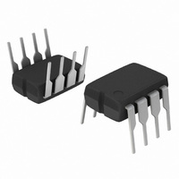
MC33262PG ON Semiconductor, MC33262PG Datasheet - Page 6

MC33262PG
Manufacturer Part Number
MC33262PG
Description
IC PFC CONTROLLER CRM 8DIP
Manufacturer
ON Semiconductor
Datasheet
1.MC34262DG.pdf
(19 pages)
Specifications of MC33262PG
Mode
Critical Conduction (CRM)
Current - Startup
250µA
Voltage - Supply
12 V ~ 28 V
Operating Temperature
-40°C ~ 105°C
Mounting Type
Through Hole
Package / Case
8-DIP (0.300", 7.62mm)
Maximum Operating Temperature
+ 105 C
Mounting Style
Through Hole
Minimum Operating Temperature
- 40 C
Lead Free Status / RoHS Status
Lead free / RoHS Compliant
Frequency - Switching
-
Lead Free Status / Rohs Status
Lead free / RoHS Compliant
Other names
MC33262PGOS
Available stocks
Company
Part Number
Manufacturer
Quantity
Price
Company:
Part Number:
MC33262PG
Manufacturer:
ON
Quantity:
5 510
Company:
Part Number:
MC33262PG
Manufacturer:
ON Semiconductor
Quantity:
8 150
Part Number:
MC33262PG
Manufacturer:
ON/安森美
Quantity:
20 000
Introduction
legislation on line- - current harmonic content, there is an
ever increasing demand for an economical method of
obtaining a unity power factor. This data sheet describes a
monolithic control IC that was specifically designed for
power factor control with minimal external components. It
offers the designer a simple, cost- - effective solution to
obtain the benefits of active power factor correction.
use a bridge rectifier and a bulk storage capacitor to derive
raw dc voltage from the utility ac line, Figure 15.
when the instantaneous ac voltage exceeds the capacitor
voltage. This occurs near the line voltage peak and results
in a high charge current spike, Figure 16. Since power is
only taken near the line voltage peaks, the resulting spikes
of current are extremely nonsinusoidal with a high content
of harmonics. This results in a poor power factor condition
where the apparent input power is much higher than the real
power. Power factor ratios of 0.5 to 0.7 are common.
either a passive or an active input circuit. Passive circuits
usually contain a combination of large capacitors,
inductors, and rectifiers that operate at the ac line
frequency. Active circuits incorporate some form of a high
Line
AC
With the goal of exceeding the requirements of
Most electronic ballasts and switching power supplies
This simple rectifying circuit draws power from the line
Power factor correction can be achieved with the use of
8.0
4.0
16
12
0
0
Figure 16. Uncorrected Power Factor Circuit
Rectifiers
Figure 14. Supply Current
versus Supply Voltage
10
V
CC
, SUPPLY VOLTAGE (V)
+
Bulk
Storage
Capacitor
20
Converter
V
Current Sense = 0 V
Multiplier = 0 V
C
f = 50 kHz
T
A
FB
L
= 25C
= 1.0 nF
= 0 V
30
FUNCTIONAL DESCRIPTION
http://onsemi.com
Load
40
6
frequency switching converter for the power processing,
with the boost converter being the most popular topology,
Figure 17. Since active input circuits operate at a frequency
much higher than that of the ac line, they are smaller,
lighter in weight, and more efficient than a passive circuit
that yields similar results. With proper control of the
preconverter, almost any complex load can be made to
appear resistive to the ac line, thus significantly reducing
the harmonic current content.
conduction, current- - mode power factor controllers
specifically designed for use in off- - line active
preconverters. These devices provide the necessary
features required to significantly enhance poor power
factor loads by keeping the ac line current sinusoidal and
in phase with the line voltage.
Rectified
AC Line
Voltage
AC Line
Current
DC
The MC34262, MC33262 are high performance, critical
9.0
8.0
7.0
V
14
13
12
10
11
- - 55
pk
0
0
Figure 15. Undervoltage Lockout Thresholds
Figure 17. Uncorrected Power Factor
- - 25
T
versus Temperature
A
Line Sag
0
, AMBIENT TEMPERATURE (C)
Minimum Operating Threshold
Input Waveforms
Startup Threshold
(V
(V
CC
CC
25
Decreasing)
Increasing)
50
75
100
125


