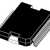
L9952XP STMicroelectronics, L9952XP Datasheet - Page 20

L9952XP
Manufacturer Part Number
L9952XP
Description
IC PWR MANAGEMENT SYST PWRSSO36
Manufacturer
STMicroelectronics
Datasheet
1.L9952GXPTR.pdf
(68 pages)
Specifications of L9952XP
Applications
Automotive
Voltage - Supply
6 V ~ 18 V
Operating Temperature
-40°C ~ 150°C
Mounting Type
Surface Mount
Package / Case
PowerSSO-36 Exposed Bottom Pad
Product
Fan / Motor Controllers / Drivers
Mounting Style
SMD/SMT
Lead Free Status / RoHS Status
Lead free / RoHS Compliant
Current - Supply
-
Lead Free Status / Rohs Status
Lead free / RoHS Compliant
Available stocks
Company
Part Number
Manufacturer
Quantity
Price
Company:
Part Number:
L9952XP
Manufacturer:
st
Quantity:
10 000
Part Number:
L9952XP
Manufacturer:
ST
Quantity:
20 000
Company:
Part Number:
L9952XPTR
Manufacturer:
st
Quantity:
10 000
Company:
Part Number:
L9952XPTR
Manufacturer:
MICREL
Quantity:
304
Part Number:
L9952XPTR
Manufacturer:
ST
Quantity:
20 000
Description
2.12
2.13
Note:
2.14
20/68
1
2
V1, V2 fail
The V
In case of a drop below the V
bits are latched. The fail bits are cleared by a dedicated SPI command.
If 4ms after turn on of the regulator the V
(independent for V1,2 ), the L9952GXP will identify a short circuit condition at the related
regulator output and the regulator will be switched off.
In case of a V1 failure the device enters V
In case of a V2 failure the SHT5V2 bit (SR0 Bit12) is set.
Low side driver outputs Rel1, Rel2
The outputs Rel1, Rel2 (R
loads.
Typical relays used have the following characteristics:
Relay type 1:
Relay type 2:
The outputs provide an active output zener clamping (40V) feature for the demagnetisation
of the relay coil, even though a load dump condition exists. In case of watchdog failure the
relay drivers will be switched off and the low side driver control bits are cleared.
Due to relays bouncing, high dV/dt and/or dI/dt transients may occur on the low side driver
outputs. In case high currents are switched (for example window lift motor), due to parasitic
capacitive inductive coupling from load side of relays to the relays coils, the Absolute
Maximum Ratings of the Low Side driver outputs may be exceeded. In order to avoid this, it
is recommended to place a 10nF capacitor at the Rel1, Rel2 outputs to GND.
If a hard short circuit to V
required with T
circuit of given di/dt = 5A/µs).
PWM inputs
The inputs PWM 1,2 can be used to control the output drivers Out1..4 and OUT_HS with a
PWM signal. Each PWM input can be mapped individually to each of the above listed
outputs according to the SPI settings.
–
–
–
–
1,
and V
closed armature: R = 160 Ω +10%, L= 300mH
open armature: R = 160 Ω +10%, L= 240mH
closed armature: R= 220 Ω +10%, L= 420mH
open armature: R= 220 Ω +10%, L= 330mH
2
RC
regulator output voltages are monitored.
> 1µs, R ≥ 1 Ω (see block diagram, the value is given for an output short
BAT
DSon
is possible at the "Low Side Driver" outputs, an RC network is
1,
Doc ID 13518 Rev 5
V
= 2 Ω typ. @25 °C) are specially designed to drive relay
2
– fail thresholds (V
1,2
BAT
voltage is below the V
- standby mode automatically.
1,2
< 2V,typ for t > 2us), the V
1,2
fail thresholds,
L9952GXP
1,2
- fail


