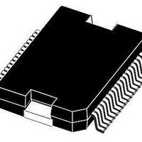
L9952XP STMicroelectronics, L9952XP Datasheet - Page 55

L9952XP
Manufacturer Part Number
L9952XP
Description
IC PWR MANAGEMENT SYST PWRSSO36
Manufacturer
STMicroelectronics
Datasheet
1.L9952GXPTR.pdf
(68 pages)
Specifications of L9952XP
Applications
Automotive
Voltage - Supply
6 V ~ 18 V
Operating Temperature
-40°C ~ 150°C
Mounting Type
Surface Mount
Package / Case
PowerSSO-36 Exposed Bottom Pad
Product
Fan / Motor Controllers / Drivers
Mounting Style
SMD/SMT
Lead Free Status / RoHS Status
Lead free / RoHS Compliant
Current - Supply
-
Lead Free Status / Rohs Status
Lead free / RoHS Compliant
Available stocks
Company
Part Number
Manufacturer
Quantity
Price
Company:
Part Number:
L9952XP
Manufacturer:
st
Quantity:
10 000
Part Number:
L9952XP
Manufacturer:
ST
Quantity:
20 000
Company:
Part Number:
L9952XPTR
Manufacturer:
st
Quantity:
10 000
Company:
Part Number:
L9952XPTR
Manufacturer:
MICREL
Quantity:
304
Part Number:
L9952XPTR
Manufacturer:
ST
Quantity:
20 000
L9952GXP
8.1.1
Table 36.
Access
Reset
Name
Bit
GO
V1
21
w
0
V
GO
Control register 0
While writing to the control register 0, the status register 0 can be read at the DO-Output of
the SPI.
Control register 0
20
Table 37.
Table 38.
Table 39.
Table 40.
w
0
bat
OUT_HS
x
HSx2
On_V21
0
0
0
0
1
1
2
TRIG
19
0
w
0
Name / state
Name / state
Name / state
Name / state
OUT_HS
RELx
V21
HSx1
ON
18
w
0
0
1
0
0
1
1
0
0
1
5V2
Configuration bit HSxx
Configuration bit OUT_HSx
Configuration bit RELx
Configuration bit On_V2x
On_V20
V20
17
ON
w
0
OUT_HS
0
HSx0 Defines the output configuration of the High Side Drivers 1-4
REL
0
1
0
1
0
1
16
0
w
0
2
REL
15
Defines the output configuration of the High Side Driver OUT_HS
Driver is OFF in all modes
Driver is ON in active mode, off in standby mode
Driver is cyclic ON with the timing of Timer 1 in active mode and standby
modes
Driver is cyclic ON with the timing of Timer 2 in active mode and standby
modes
Driver is controlled by the PWM1 Input
Driver is controlled by the PWM2 Input
Defines the Output configuration of the low side relay drivers 1/2
Driver is OFF in all modes
Driver is ON in active mode (off in standby mode)
Defines in which modes the voltage regulator 2 is on
Voltage regulator 2 is OFF in all modes
w
0
1
OUT
HS2
14
w
0
Doc ID 13518 Rev 5
OUT
HS1
13
w
0
OUT
HS0
12
w
0
HS
11
42
w
0
HS
10
41
w
0
Driver ON Signals
Definition/ function
Definition/ function
Definition/ function
Definition/ function
HS
40
w
9
0
HS
32
w
8
0
SPI control and status registers
HS
31
w
7
0
HS
30
w
6
0
HS
22
w
5
0
HS
21
w
4
0
HS
20
w
3
0
HS
12
w
2
0
HS
11
w
1
0
55/68
HS
10
w
0
0


