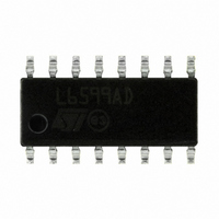
L6599ADTR STMicroelectronics, L6599ADTR Datasheet - Page 26

L6599ADTR
Manufacturer Part Number
L6599ADTR
Description
IC RESONANT CONVRTR CTRLR 16SOIC
Manufacturer
STMicroelectronics
Specifications of L6599ADTR
Applications
Resonant Converter Controller
Voltage - Supply
8.85 V ~ 16 V
Current - Supply
3.5mA
Operating Temperature
0°C ~ 105°C
Mounting Type
Surface Mount
Package / Case
16-SOIC (3.9mm Width)
Operating Temperature Classification
Automotive
Mounting
Surface Mount
Pin Count
16
Operating Supply Voltage
8.15 V, 10.7 V, 17 V
Maximum Operating Temperature
+ 150 C
Minimum Operating Temperature
- 40 C
Mounting Style
SMD/SMT
For Use With
497-10542 - BOARD EVAL BASED ON L6599497-8429 - BOARD ADAPTER L6599/STP12NM50N497-5496 - EVAL BOARD FOR L6599
Lead Free Status / RoHS Status
Lead free / RoHS Compliant
Voltage - Input
-
Lead Free Status / Rohs Status
Compliant
Other names
497-8519-2
Available stocks
Company
Part Number
Manufacturer
Quantity
Price
Company:
Part Number:
L6599ADTR
Manufacturer:
U-BLOX
Quantity:
21 000
Part Number:
L6599ADTR
Manufacturer:
ST
Quantity:
20 000
Part Number:
L6599ADTR-2LF
Manufacturer:
ST
Quantity:
20 000
Application information
26/36
The circuit shown in
series to C
operates like a capacitive current divider; C
less and will be a low-loss type, the sense resistor R
Equation 7
and C
If the resistor R
kΩ), the circuit operates like a divider of the ripple voltage across the resonant capacitor Cr,
which, in turn, is related to its current through the reactance of Cr. Again, C
selected equal to Cr/100 or less, this time not necessarily a low-loss type, while R
(provided it is << R
Equation 8
where the reactance of C
I
Whichever circuit one is going to use, the calculated values of Rs or R
considered just a first cut value that needs to be adjusted after experimental verification.
OCP is effective in limiting primary-to-secondary energy flow in case of an overload or an
output short circuit, but the output current through the secondary winding and rectifiers
under these conditions might be so high to endanger converter’s safety if continuously
flowing. To prevent any damage during these conditions it is customary to force converter’s
intermittent operation, in order to bring the average output current to values such that the
thermal stress for the transformer and the rectifiers can be easily handled.
With the L6599A the designer can program externally the maximum time T
converter is allowed to run overloaded or under short circuit conditions. Overloads or short
circuits lasting less than T
with immunity to short duration phenomena. If, instead, T
protection (OLP) procedure is activated that shuts down the L6599A and, in case of
continuous overload/short circuit, results in continuous intermittent operation with a user-
defined duty cycle.
Crpk
= I
B
Crpkx
will be such that R
A
. Again, C
is small (not above some hundred Ω, just to limit current spiking) the circuit
A
in series to C
A
) according to:
Figure 28
B
will be such that R
A
SH
B
(X
·C
will not cause any other action, hence providing the system
CA
B
A
b can be operated in two different ways. If the resistor R
Doc ID 15308 Rev 5
is in the range of 10 /f
is not small (in this case it will be typically selected in the ten
) and Cr (X
R
R
B
B
=
=
I
0
Crpkx
I
8 .
0
Crpkx
B
8 .
Cr
A
π
·C
) should be calculated at the frequency where
will be typically selected equal to Cr/100 or
π
B
⎛
⎜ ⎜
⎝
R
1
is in the range of 10 /f
2
A
+
X
+
C
Cr
C
B
X
A
r
min
will be selected as:
2
C
⎞
⎟ ⎟
⎠
A
.
SH
is exceeded an overload
min
B
should be
.
A
SH
will be typically
that the
B
L6599A
A
in


