AD536AKD Analog Devices Inc, AD536AKD Datasheet - Page 10
AD536AKD
Manufacturer Part Number
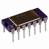
AD536AKD
Description
IC TRUE RMS/DC CONV 14-CDIP
Manufacturer
Analog Devices Inc
Datasheet
1.AD536AJHZ.pdf
(16 pages)
Specifications of AD536AKD
Rohs Status
RoHS non-compliant
Current - Supply
1.2mA
Voltage - Supply
5.0V ~ 36V, ±3.0V ~ 18V
Mounting Type
Through Hole
Package / Case
14-CDIP (0.300", 7.62mm)
Accuracy %
0.2%
Bandwidth
450kHz
Supply Current
1.2mA
Power Dissipation Pd
500mW
Supply Voltage Range
5V To 36V
Digital Ic Case Style
DIP
No. Of Pins
14
Lead Free Status / RoHS Status
Contains lead / RoHS non-compliant
Available stocks
Company
Part Number
Manufacturer
Quantity
Price

Part Number:
AD536AKD
Manufacturer:
ADI/亚德诺
Quantity:
20 000
Company:
Part Number:
AD536AKDZ
Manufacturer:
Analog Devices Inc
Quantity:
135


AD536A
The primary disadvantage in using a large C
is that the settling time for a step change in input level is
increased proportionately. Figure 12 illustrates that the
relationship between C
each microfarad of C
decreasing signals as it is for increasing signals. The values in
Figure 12 are for decreasing signals. Settling time also increases
for low signal levels, as shown in Figure 13.
A better method to reduce output ripple is the use of a postfilter.
Figure 14 shows a suggested circuit. If a single-pole filter is used
(C3 removed, R
value of C
settling time is increased. For example, with C
= 2.2 μF, the ripple for a 60 Hz input is reduced from 10% of
reading to approximately 0.3% of reading.
1
PERCENT DC ERROR AND PERCENT RIPPLE (PEAK)
0.01
100
0.1
Figure 12. Error/Settling Time Graph for Use with the Standard RMS
10
1
1
10.0
7.5
5.0
2.5
1.0
VALUES FOR C
1% SETTLING TIME
FOR STATED % OF READING
AVERAGING ERROR
ACCURACY ± 20% DUE TO
COMPONENT TOLERANCE
1m
AV
, the ripple is reduced, as shown in Figure 15, and
Connection (See Figure 6 Through Figure 8)
10
X
Figure 13. Settling Time vs. Input Level
shorted) and C2 is approximately twice the
AV
10m
INPUT FREQUENCY (Hz)
AND
AV
1
AV
. The settling time is twice as great for
100
and 1% settling time is 115 ms for
rms INPUT LEVEL (V)
100m
1k
10k
AV
1
AV
to remove ripple
= 1 μF and C2
100k
100
10
1
0.1
0.01
10
Rev. D | Page 10 of 16
The settling time, however, is increased by approximately a
factor of 3. Therefore, the values of C
to permit faster settling times while still providing substantial
ripple reduction.
The two-pole postfilter uses an active filter stage to provide
even greater ripple reduction without substantially increasing
the settling times over a circuit with a one-pole filter. The values
of C
settling times for a constant amount of ripple. Caution should
be exercised in choosing the value of C
is dependent on this value and is independent of the postfilter.
For a more detailed explanation of these topics, refer to the RMS to
DC Conversion Application Guide, 2nd Edition, available online
from Analog Devices, Inc., at www.analog.com.
AV
, C2, and C3 can then be reduced to allow extremely fast
0.1
10
1
C
10
Figure 15. Performance Features of Various Filter Types
(See Figure 6 to Figure 8 for Standard RMS Connection)
–V
AV
BUF OUT
V
IN
BUF IN
S
1
FOR SINGLE POLE, SHORT Rx, REMOVE C3.
+
–
C
–V
V
NC
C2
dB
AV
IN
PEAK-TO-PEAK
RIPPLE (ONE POLE)
C
S
AV
1
2
3
4
5
6
7
= 1µF, C2 = 2.2µF
Figure 14. Two-Pole Postfilter
AD536A
DC ERROR
C
(ALL FILTERS)
AV
Rx = 0Ω
BUF
100
= 1µF
25kΩ
PEAK-TO-PEAK RIPPLE
C
C2 = C3 = 2.2µF (TWO-POLE)
ABSOLUTE
SQUARER/
CURRENT
AV
FREQUENCY (Hz)
DIVIDER
MIRROR
VALUE
24kΩ
Rx
= 1µF
PEAK-TO-PEAK RIPPLE
C
25kΩ
AV
= 1µF
AV
14
13
12
11
10
AV
9
8
C3
and C2 can be reduced
1k
, because the dc error
1
+V
NC
NC
NC
COM
R
I
OUT
L
S
–
+
+V
S
V
rms
OUT
10k
Related parts for AD536AKD
Image
Part Number
Description
Manufacturer
Datasheet
Request
R

Part Number:
Description:
±1.7g Dual-Axis IMEMS Accelerometer Evaluation Board
Manufacturer:
Analog Devices Inc
Datasheet:

Part Number:
Description:
Inertial Sensor Evaluation System
Manufacturer:
Analog Devices Inc
Datasheet:
Part Number:
Description:
Manufacturer:
Analog Devices Inc
Datasheet:
Part Number:
Description:
Manufacturer:
Analog Devices Inc
Datasheet:
Part Number:
Description:
Manufacturer:
Analog Devices Inc
Datasheet:
Part Number:
Description:
Manufacturer:
Analog Devices Inc
Datasheet:
Part Number:
Description:
Manufacturer:
Analog Devices Inc
Datasheet:
Part Number:
Description:
Manufacturer:
Analog Devices Inc
Datasheet:
Part Number:
Description:
Manufacturer:
Analog Devices Inc
Datasheet:
Part Number:
Description:
Manufacturer:
Analog Devices Inc
Datasheet:
Part Number:
Description:
Manufacturer:
Analog Devices Inc
Datasheet:
Part Number:
Description:
Manufacturer:
Analog Devices Inc
Datasheet:
Part Number:
Description:
Manufacturer:
Analog Devices Inc
Datasheet: