AD536AKD Analog Devices Inc, AD536AKD Datasheet - Page 2
AD536AKD
Manufacturer Part Number
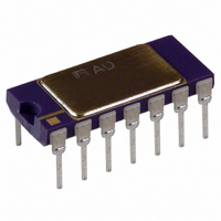
AD536AKD
Description
IC TRUE RMS/DC CONV 14-CDIP
Manufacturer
Analog Devices Inc
Datasheet
1.AD536AJHZ.pdf
(16 pages)
Specifications of AD536AKD
Rohs Status
RoHS non-compliant
Current - Supply
1.2mA
Voltage - Supply
5.0V ~ 36V, ±3.0V ~ 18V
Mounting Type
Through Hole
Package / Case
14-CDIP (0.300", 7.62mm)
Accuracy %
0.2%
Bandwidth
450kHz
Supply Current
1.2mA
Power Dissipation Pd
500mW
Supply Voltage Range
5V To 36V
Digital Ic Case Style
DIP
No. Of Pins
14
Lead Free Status / RoHS Status
Contains lead / RoHS non-compliant
Available stocks
Company
Part Number
Manufacturer
Quantity
Price

Part Number:
AD536AKD
Manufacturer:
ADI/亚德诺
Quantity:
20 000
Company:
Part Number:
AD536AKDZ
Manufacturer:
Analog Devices Inc
Quantity:
135


AD536A
TABLE OF CONTENTS
Features .............................................................................................. 1
General Description ......................................................................... 1
Functional Block Diagram .............................................................. 1
Revision History ............................................................................... 2
Specifications ..................................................................................... 3
Absolute Maximum Ratings ............................................................ 5
Pin Configurations and Function Descriptions ........................... 6
Applications Information ................................................................ 8
REVISION HISTORY
8/08—Rev. C to Rev. D
Changes to Features Section............................................................ 1
Changes to General Description Section ...................................... 1
Changes to Figure 1 .......................................................................... 1
Changes to Table 2 ............................................................................ 5
Change to Figure 2 ........................................................................... 5
Changes to Figure 15 ...................................................................... 10
Changes to Connections for dB Operation Section ................... 11
Changes to Figure 17 ...................................................................... 12
Changes to Frequency Response Section .................................... 12
Updated Outline Dimensions ....................................................... 14
Changes to Ordering Guide .......................................................... 15
3/06—Rev. B to Rev. C
Updated Format .................................................................. Universal
Changed Product Description to General Description ............... 1
Changes to General Description .................................................... 1
Changes to Table 1 ............................................................................ 3
Changes to Table 2 ............................................................................ 5
Added Pin Configurations and Function Descriptions .............. 6
Changed Standard Connection to Typical Connections ............. 8
Changed Single Supply Connection to Single Supply
Operation ........................................................................................... 9
Changes to Connections for dB Operation ................................. 11
Changes to Figure 17 ...................................................................... 12
Updated Outline Dimensions ....................................................... 14
Changes to Ordering Guide .......................................................... 15
6/99—Rev. A to Rev. B
1/76—Revision 0: Initial Version
ESD Caution .................................................................................. 5
Typical Connections .................................................................... 8
Rev. D | Page 2 of 16
Theory of Operation ...................................................................... 11
Outline Dimensions ....................................................................... 14
Optional External Trims For High Accuracy ............................8
Single-Supply Operation ..............................................................9
Choosing the Averaging Time Constant ....................................9
Connections for dB Operation ................................................. 11
Frequency Response .................................................................. 12
AC Measurement Accuracy and Crest Factor ........................ 12
Ordering Guide .......................................................................... 15
Related parts for AD536AKD
Image
Part Number
Description
Manufacturer
Datasheet
Request
R

Part Number:
Description:
±1.7g Dual-Axis IMEMS Accelerometer Evaluation Board
Manufacturer:
Analog Devices Inc
Datasheet:

Part Number:
Description:
Inertial Sensor Evaluation System
Manufacturer:
Analog Devices Inc
Datasheet:
Part Number:
Description:
Manufacturer:
Analog Devices Inc
Datasheet:
Part Number:
Description:
Manufacturer:
Analog Devices Inc
Datasheet:
Part Number:
Description:
Manufacturer:
Analog Devices Inc
Datasheet:
Part Number:
Description:
Manufacturer:
Analog Devices Inc
Datasheet:
Part Number:
Description:
Manufacturer:
Analog Devices Inc
Datasheet:
Part Number:
Description:
Manufacturer:
Analog Devices Inc
Datasheet:
Part Number:
Description:
Manufacturer:
Analog Devices Inc
Datasheet:
Part Number:
Description:
Manufacturer:
Analog Devices Inc
Datasheet:
Part Number:
Description:
Manufacturer:
Analog Devices Inc
Datasheet:
Part Number:
Description:
Manufacturer:
Analog Devices Inc
Datasheet:
Part Number:
Description:
Manufacturer:
Analog Devices Inc
Datasheet: