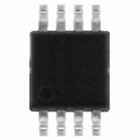
STTS75DS2F STMicroelectronics, STTS75DS2F Datasheet - Page 19

STTS75DS2F
Manufacturer Part Number
STTS75DS2F
Description
IC TEMP SENSOR DGTL WCHDG 8MSOP
Manufacturer
STMicroelectronics
Datasheet
1.STTS75M2F.pdf
(41 pages)
Specifications of STTS75DS2F
Function
Temp Sensor, Watchdog
Topology
ADC (Sigma Delta), Comparator, Register Bank
Sensor Type
Internal
Sensing Temperature
-55°C ~ 125°C
Output Type
I²C™/SMBus™
Output Alarm
Yes
Output Fan
No
Voltage - Supply
2.7 V ~ 5.5 V
Operating Temperature
-55°C ~ 125°C
Mounting Type
Surface Mount
Package / Case
8-MSOP, Micro8™, 8-uMAX, 8-uSOP,
Full Temp Accuracy
+/- 3 C
Digital Output - Bus Interface
Serial (2-Wire, I2C)
Digital Output - Number Of Bits
12 bit
Maximum Operating Temperature
+ 125 C
Minimum Operating Temperature
- 55 C
For Use With
497-8844 - EVAL DAUGHTER STTS75 8-TSSOP497-8419 - BOARD ST72651AR6/STTS75/STLM20
Lead Free Status / RoHS Status
Lead free / RoHS Compliant
Other names
497-6331-2
Available stocks
Company
Part Number
Manufacturer
Quantity
Price
Company:
Part Number:
STTS75DS2F
Manufacturer:
NXP
Quantity:
1 104
Company:
Part Number:
STTS75DS2F
Manufacturer:
STMicroelectronics
Quantity:
1 908
STTS75
3.1.3
3.1.4
Temperature register
The temperature register is a two-byte (16-bit) “Read only” register (see
page
complement format, and the contents of this register are updated each time the A/D
conversion is finished.
The user can read data from the temperature register at any time. When a T-to-D conversion
is completed, the new data is loaded into a comparator buffer to evaluate fault conditions
and will update the temperature register if a read cycle is not ongoing. If a READ is ongoing,
the previous temperature will be read. Accessing the STTS75 continuously without waiting
at least one conversion time between communications will prevent the device from updating
the temperature register with a new temperature conversion result. Consequently, the
STTS75 should not be accessed continuously with a wait time of less than t
Depending on the A/D conversion resolution, the 9-, 10-, 11- or 12-bit MSBs of the register
will contain temperature data. All unused bits following the digital temperature will be zero.
The MSB (bit 15) of the temperature register denotes whether the temperature data is
positive or negative. A '0' in bit 15 is positive and a '1' is negative.
Table 9.
Overlimit temperature register (T
The T
programmable upper trip-point temperature for the thermal alarm in two’s complement
format (see
0000 0000 0000).
The format of the T
the T
The MSB position contains the sign bit for the digital temperature and bit14 contains the
temperature MSB.
The resolution setting for the A/D conversion determines how many bits of the T
are used by the thermal alarm. For example, for 9-bit conversions, the trip-point temperature
is defined by the 9 MSBs of the T
Keys:
STTS75
Bytes
Bits
OS
19). Digital temperatures from the ADC are stored in the temperature register in two’s
OS
TMSB = temperature MSB
TLSB = temperature LSB
register are hardwired to zero, so data written to these register bits will be ignored.
register is a two-byte (16-bit) READ/WRITE register that stores the user-
SB = two’s complement sign bit
TD = temperature data
MSB
SB
15
Table 10 on page
Temperature register format
TMSB TD TD TD TD TD TD
14
OS
register is identical to that of the temperature register. The 4 LSBs of
13
MS byte
12
Doc ID 13298 Rev 11
THSB
20). This register defaults to 80 °C at power-up (i.e., 0101
11
OS
register, and all remaining bits are “Don’t cares.”
10
OS
9
)
8
9-bit
LSB
7
10-bit
LSB
6
11-bit
LSB
TLSB
5
Functional description
LS byte
12-bit
LSB
Table 9 on
4
CONV
3 2 1
0 0 0
OS
(max).
register
19/41
LSB
0
0


