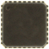
ADT7462ACPZ-5RL7 ON Semiconductor, ADT7462ACPZ-5RL7 Datasheet - Page 14

ADT7462ACPZ-5RL7
Manufacturer Part Number
ADT7462ACPZ-5RL7
Description
IC TEMP/VOLT MONITOR 32-LFCSP
Manufacturer
ON Semiconductor
Datasheet
1.ADT7462ACPZ-5RL7.pdf
(81 pages)
Specifications of ADT7462ACPZ-5RL7
Function
Fan Control, Temp Monitor
Topology
ADC, Comparator, Multiplexer, Register Bank
Sensor Type
External & Internal
Sensing Temperature
-40°C ~ 125°C, External Sensor
Output Type
SMBus™
Output Alarm
No
Output Fan
Yes
Voltage - Supply
3 V ~ 5.5 V
Operating Temperature
-40°C ~ 125°C
Mounting Type
Surface Mount
Package / Case
32-LFCSP
Supply Voltage (max)
5.5 V
Supply Voltage (min)
3 V
Maximum Operating Temperature
+ 125 C
Minimum Operating Temperature
- 40 C
Lead Free Status / RoHS Status
Lead free / RoHS Compliant
Other names
ADT7462ACPZ-500RL7
ADT7462ACPZ-500RL7
ADT7462ACPZ-500RL7TR
ADT7462ACPZ-500RL7TR
ADT7462ACPZ-5RL7TR
ADT7462ACPZ-500RL7
ADT7462ACPZ-500RL7TR
ADT7462ACPZ-500RL7TR
ADT7462ACPZ-5RL7TR
Available stocks
Company
Part Number
Manufacturer
Quantity
Price
Company:
Part Number:
ADT7462ACPZ-5RL7
Manufacturer:
ON Semiconductor
Quantity:
135
Configuration Option 5
voltages, and fans for Processor 2 in a dual processor system.
Features of Configuration Option 5 include the following:
•
•
•
•
•
•
•
•
•
•
Option 5 is chosen.
Configuration Option 5 is used to monitor temperature,
Figure 23 shows the pin configuration when Configuration
One local and two remote temperature channels
Up to three PWM drives and up to six TACH inputs
Voltage monitoring
Two +12V
+3.3V
Mem_Core (+1.969V)
+1.8 V
Two +1.5V
+1.2V (V
RESET I/O
TACH1
TACH2
TACH3
TACH4
+12V1
+12V2
GND
Figure 23. Configuration Option 5
CCP2
V
CC
1
2
3
4
5
6
7
8
)
PIN 1
INDICATOR
(Not to Scale)
ADT7462
TOP VIEW
24
23
22
21
20
19
18
17
V
+1.8V
TACH8
TACH7
D3–
D3+
D2−
D2+
CCP2
http://onsemi.com
14
Table 6. Configuration Option 5
†If VIDs are selected, these pins are configured as VIDs. To
*It is not possible to configure +1.5V monitoring on Pin 29 and
31
32
Pin
29*
13
15
16
19
20
21
22
23
24
25
26
27
28
1
2
3
4
†*
7
8
enable VIDs, set Bit 7 of Pin Configuration Register 1 (0x10) = 1.
THERM1 on Pin 28. Pin 28 must both be configured as either
+1.5V monitoring or as THERM I/O (see Table 47).
†
†
†
†
†
†
VR_HOT2
FAN2MAX
THERM1/
THERM2/
Function
TACH1
TACH2
TACH3
TACH4
TERM1
TACH7
TACH8
+12V1
+12V2
PWM1
PWM2
SCSI_
V
+3.3V
+2.5V
+1.8V
+1.2V
+1.5V
+1.5V
D3+
D3−
CCP2
Configuration Register
Pin Configuration Reg 1
Pin Configuration Reg 1
Pin Configuration Reg 1
Pin Configuration Reg 1
Pin Configuration Reg 1
Pin Configuration Reg 2
Pin Configuration Reg 2
Pin Configuration Reg 1
Pin Configuration Reg 1
Pin Configuration Reg 1
Pin Configuration Reg 1
Pin Configuration Reg 2
Pin Configuration Reg 2
Pin Configuration Reg 2
Pin Configuration Reg 3
Pin Configuration Reg 3
Pin Configuration Reg 3
Pin Configuration Reg 3
Pin Configuration Reg 4
Pin Configuration Reg 4
Pin Configuration Reg 4
Pin Configuration Reg 4
Bit 4 = 1
Bit 3 = 1
Bit 2 = 1
Bit 1 = 1
Bit 0 = 0
Bit 7 = 0
Bit 6 = 0
Bit 6 = 0
Bit 6 = 0
Bit 5 = 1
Bit 5 = 1
Bit 3 = 1
Bit 2 = 1
Bits [1:0] = 10
Bits [7:6] = 00
Bits [5:4] = 01
Bits [3:2] = 1×
Bit 1 = 0
See Table 51
See Table 51
Bit 3 = 1
Bit 2 = 1
Bit Value


