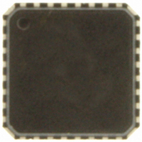
ADT7462ACPZ-5RL7 ON Semiconductor, ADT7462ACPZ-5RL7 Datasheet - Page 37

ADT7462ACPZ-5RL7
Manufacturer Part Number
ADT7462ACPZ-5RL7
Description
IC TEMP/VOLT MONITOR 32-LFCSP
Manufacturer
ON Semiconductor
Datasheet
1.ADT7462ACPZ-5RL7.pdf
(81 pages)
Specifications of ADT7462ACPZ-5RL7
Function
Fan Control, Temp Monitor
Topology
ADC, Comparator, Multiplexer, Register Bank
Sensor Type
External & Internal
Sensing Temperature
-40°C ~ 125°C, External Sensor
Output Type
SMBus™
Output Alarm
No
Output Fan
Yes
Voltage - Supply
3 V ~ 5.5 V
Operating Temperature
-40°C ~ 125°C
Mounting Type
Surface Mount
Package / Case
32-LFCSP
Supply Voltage (max)
5.5 V
Supply Voltage (min)
3 V
Maximum Operating Temperature
+ 125 C
Minimum Operating Temperature
- 40 C
Lead Free Status / RoHS Status
Lead free / RoHS Compliant
Other names
ADT7462ACPZ-500RL7
ADT7462ACPZ-500RL7
ADT7462ACPZ-500RL7TR
ADT7462ACPZ-500RL7TR
ADT7462ACPZ-5RL7TR
ADT7462ACPZ-500RL7
ADT7462ACPZ-500RL7TR
ADT7462ACPZ-500RL7TR
ADT7462ACPZ-5RL7TR
Available stocks
Company
Part Number
Manufacturer
Quantity
Price
Company:
Part Number:
ADT7462ACPZ-5RL7
Manufacturer:
ON Semiconductor
Quantity:
135
following procedure:
PWM
remains the same. The higher the PWM
smaller the effective T
speed (100%) at a lower temperature.
fan runs at full speed for different PWM
easily calculated by:
The T
T
For a given T
Figure 59. Increasing PWM
RANGE
T
1. Determine the maximum operating temperature for
2. Determine experimentally the fan speed (PWM
3. Determine the slope of the required control loop to
4. Using the ADT7462 evaluation software, this
Figure 58. Adjusting PWM
MIN
MAX
that channel (for example, 70°C).
duty cycle value) that does not exceed the
temperature at the worst−case operating points.
(For example, 70°C is reached when the fans are
running at 50% PWM duty cycle.)
meet these requirements.
functionality can be graphically programmed and
visualized.
RANGE
100%
100%
50%
33%
50%
33%
25%
10%
is changed, T
0%
0%
is implemented as a slope, which means that as
= T
MIN
RANGE
or fan control slope is determined by the
T
+ (Max DC − Min DC) × T
T
MIN
MIN
RANGE
RANGE
value, the temperature at which the
T
RANGE
305C
305C
; that is, the fan reaches full
405C
changes, but the actual slope
455C
MIN
405C
MIN
545C
Changes Effective
Affects T
MIN
MIN
values can be
RANGE
RANGE
value, the
http://onsemi.com
/170
37
T
T
Max DC is the maximum duty cycle (100%) = 255 decimal.
Min DC is equal to PWM
T
Example 1
and PWM
T
T
T
T
Example 2
and PWM
T
T
T
T
Example 3
and PWM
T
T
T
T
Example 4
and PWM
T
T
T
T
Selecting a T
channel: local, Remote 1, Remote 2, and Remote 3. Bits
[7:4] (RANGE) of Register 0x60 to Register 0x63 define the
T
and Table 82).
Summary of T
temperature at which the fan reaches full speed can be
calculated by:
PWM duty cycle.
T
PWM duty cycle to temperature slope. The effective
MAX
MIN
RANGE
MAX
MAX
MAX
MAX
MAX
MAX
MAX
MAX
MAX
MAX
MAX
MAX
MAX
MAX
MAX
MAX
RANGE
RANGE
Calculate T
Calculate T
Calculate T
Calculate T
The T
When using the automatic fan control function, the
Equation 6 holds true only when PWM
Increasing or decreasing PWM
where:
is the temperature at which the fan turns on.
is the temperature at which the fan runs full speed.
= T
= 30°C + (100% − 10%) × 40°C/170
= 30°C + (255 − 26) × 40°C/170
= 84°C (effective T
= T
= 30°C + (100% − 25%) × 40°C/170
= 30°C + (255 − 64) × 40°C/170
= 75°C (effective T
= T
= 30°C + (100% − 33%) × 40°C/170
= 30°C + (255 − 85) × 40°C/170
= 70°C (effective T
= T
= 30°C + (100% − 50%) × 40°C/170
= 30°C + (255 − 128) × 40°C/170
= 60°C (effective T
RANGE
, although the fan control still follows the same
is the PWM duty cycle vs. temperature slope.
value for each temperature channel (see Table 81
MIN
MIN
MIN
MIN
MIN
MIN
MIN
MIN
MAX
MAX
MAX
MAX
RANGE
= 10% duty cycle = 26 (decimal).
= 25% duty cycle = 64 (decimal).
= 33% duty cycle = 85 (decimal).
= 50% duty cycle = 128 (decimal).
T
+ (Max DC − Min DC) × T
+ (Max DC − Min DC) × T
+ (Max DC − Min DC) × T
+ (Max DC − Min DC) × T
RANGE
value can be selected for each temperature
MAX
, given that T
, given that T
, given that T
, given that T
+ T
Slope
Function
MIN
MIN
RANGE
RANGE
RANGE
RANGE
) T
.
MIN
MIN
MIN
MIN
RANGE
MIN
= 54°C)
= 45°C)
= 40°C)
= 30°C)
= 30°C, T
= 30°C, T
= 30°C, T
= 30°C, T
changes the effective
MIN
RANGE
RANGE
RANGE
RANGE
RANGE
RANGE
RANGE
RANGE
is equal to 33%
/170
/170
/170
/170
= 40°C,
= 40°C,
= 40°C,
= 40°C,
(eq. 6)


