GNM212R61A225MA01D Murata Electronics North America, GNM212R61A225MA01D Datasheet - Page 56
GNM212R61A225MA01D
Manufacturer Part Number
GNM212R61A225MA01D
Description
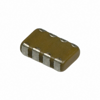
CAP 2-ARRAY 2.2UF 10V X5R 0805
Manufacturer
Murata Electronics North America
Series
GNMr
Datasheet
1.GNM212R61A225MA01D.pdf
(151 pages)
Specifications of GNM212R61A225MA01D
Capacitance
2.2µF
Voltage - Rated
10V
Dielectric Material
Ceramic
Number Of Capacitors
2
Circuit Type
Isolated
Temperature Coefficient
X5R
Tolerance
±20%
Mounting Type
Surface Mount
Package / Case
0805 (2012 Metric)
Height
0.033" (0.85mm)
Size / Dimension
0.079" L x 0.049" W (2.00mm x 1.25mm)
Lead Free Status / RoHS Status
Lead free / RoHS Compliant
Other names
GNM212R61A225MA01


9
!Note
• This PDF catalog is downloaded from the website of Murata Manufacturing co., ltd. Therefore, it’s specifications are subject to change or our products in it may be discontinued without advance notice. Please check with our
• This PDF catalog has only typical specifications because there is no space for detailed specifications. Therefore, please approve our product specifications or transact the approval sheet for product specifications before ordering.
sales representatives or product engineers before ordering.
!Note
*1: The figure indicates typical inspection.Please refer to individual specifications.
54
No.
14
15
16
17
LLL/LLA/LLM Series Specifications and Test Methods (1)
Continued from the preceding page.
Temperature
Cycle
Humidity
(Steady
Humidity
Load
High
Temperature
Load
State)
• Please read rating and !CAUTION (for storage, operating, rating, soldering, mounting and handling) in this catalog to prevent smoking and/or burning, etc.
• This catalog has only typical specifications because there is no space for detailed specifications. Therefore, please approve our product specifications or transact the approval sheet for product specifications before ordering.
Item
Appearance
Capacitance
Change
D.F.
I.R.
Dielectric
Strength
Appearance
Capacitance
Change
D.F.
I.R.
Appearance
Capacitance
Change
D.F.
I.R.
Dielectric
Strength
Appearance
Capacitance
Change
D.F.
I.R.
Dielectric
Strength
No marking defects
Within T7.5% *1
W.V.: 25V min.; 0.025 max.
W.V.: 16V max.; 0.035 max. *1
More than 10,000MΩ or 500Ω · F (Whichever is smaller)
No failure
No marking defects
Within T12.5% *1
0.05 max. *1
More than 1,000MΩ or 50Ω · F (Whichever is smaller)
No marking defects
Within T12.5% *1
0.05 max. *1
More than 500MΩ or 25Ω · F *1
(Whichever is smaller)
No failure
No marking defects
Within T12.5% *1
W.V.: 25V min.; 0.04 max.
W.V.: 16V max.; 0.05 max. *1
More than 1,000MΩ or 50Ω · F *1
(Whichever is smaller)
No failure
Specifications
Fix the capacitor to the supporting jig in the same manner and
under the same conditions as (10).
Perform the five cycles according to the four heat treatments
listed in the following table. Let sit for 24T2 hours at room
temperature, then measure.
• Initial measurement.
Sit the capacitor at 40T2°C and 90 to 95% humidity for 500T12
hours. Remove and let sit for 24T2 hours at room temperature,
then measure.
Apply the rated voltage at 40T2°C and 90 to 95% humidity for
500T12 hours. Remove and let sit for 24T2 hours at room
temperature, then measure. The charge/discharge current is
less than 50mA.
Apply 200% of the rated voltage for 1000T12 hours at the
maximum operating temperature T3°C. Let sit for 24T2 hours
at room temperature, then measure. The charge/discharge
current is less than 50mA.
•Initial measurement.
Perform a heat treatment at 150
let sit for 24T2 hours at room temperature. Perform the initial
measurement.
Apply 200% of the rated DC voltage for one hour at the
maximum operating temperature T3°C. Remove and let sit for
24T2 hours at room temperature.
Perform initial measurement. (*1)
Temp. (°C)
Time (min.)
Step
Min. Operating
Temp.
30T3
1
+0
–3
Test Method
Temp.
Room
2 to 3
2
+0
–10
°C for one hour and then
Max. Operating
Temp.
30T3
3
+3
–0
Temp.
Room
2 to 3
4
C02E.pdf
07.2.6
Related parts for GNM212R61A225MA01D
Image
Part Number
Description
Manufacturer
Datasheet
Request
R

Part Number:
Description:
BUZZER PIEZO 25VP-P SMD
Manufacturer:
Murata Electronics North America

Part Number:
Description:
CAP 4-ARRAY 680PF 100V X7R 1206
Manufacturer:
Murata Electronics North America
Datasheet:
Part Number:
Description:
CAP 4-ARRAY 1000PF 100V X7R 1206
Manufacturer:
Murata Electronics North America
Datasheet:
Part Number:
Description:
CAP 4-ARRAY 1800PF 100V X7R 1206
Manufacturer:
Murata Electronics North America
Datasheet:
Part Number:
Description:
CAP 4-ARRAY 68000PF 16V X7R 1206
Manufacturer:
Murata Electronics North America
Datasheet:

Part Number:
Description:
CAP CER 1000PF 50V 10% X7R 0402
Manufacturer:
Murata Electronics North America
Datasheet:
Part Number:
Description:
CAP CER 10000PF 16V 10% X7R 0402
Manufacturer:
Murata Electronics North America
Datasheet:

Part Number:
Description:
CAP 5.5-25PF 2.5X3.2MM SMD
Manufacturer:
Murata Electronics North America
Datasheet:

Part Number:
Description:
CAP 4.5-20PF 2.5X3.2MM SMD
Manufacturer:
Murata Electronics North America
Datasheet:

Part Number:
Description:
CAP 5.0-20PF 3.2X4.5MM SMD RED
Manufacturer:
Murata Electronics North America
Datasheet:

Part Number:
Description:
CAP 2.0-6.0PF 3.2X4.5MM SMD BLU
Manufacturer:
Murata Electronics North America
Datasheet:

Part Number:
Description:
CAP 1.4-3.0PF 3.2X4.5MM SMD BRN
Manufacturer:
Murata Electronics North America
Datasheet:

Part Number:
Description:
CAP 3.0-10PF 3.2X4.5MM SMD WHT
Manufacturer:
Murata Electronics North America
Datasheet:

Part Number:
Description:
CAP 2.0-6.0PF 4X4.5MM TOPADJ BLU
Manufacturer:
Murata Electronics North America
Datasheet:

Part Number:
Description:
CAP 8.5-40PF 4X4.5MM TOPADJ YEL
Manufacturer:
Murata Electronics North America
Datasheet: