GNM212R61A225MA01D Murata Electronics North America, GNM212R61A225MA01D Datasheet - Page 85
GNM212R61A225MA01D
Manufacturer Part Number
GNM212R61A225MA01D
Description
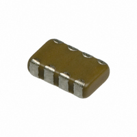
CAP 2-ARRAY 2.2UF 10V X5R 0805
Manufacturer
Murata Electronics North America
Series
GNMr
Datasheet
1.GNM212R61A225MA01D.pdf
(151 pages)
Specifications of GNM212R61A225MA01D
Capacitance
2.2µF
Voltage - Rated
10V
Dielectric Material
Ceramic
Number Of Capacitors
2
Circuit Type
Isolated
Temperature Coefficient
X5R
Tolerance
±20%
Mounting Type
Surface Mount
Package / Case
0805 (2012 Metric)
Height
0.033" (0.85mm)
Size / Dimension
0.079" L x 0.049" W (2.00mm x 1.25mm)
Lead Free Status / RoHS Status
Lead free / RoHS Compliant
Other names
GNM212R61A225MA01


!Note
• This PDF catalog is downloaded from the website of Murata Manufacturing co., ltd. Therefore, it’s specifications are subject to change or our products in it may be discontinued without advance notice. Please check with our
• This PDF catalog has only typical specifications because there is no space for detailed specifications. Therefore, please approve our product specifications or transact the approval sheet for product specifications before ordering.
sales representatives or product engineers before ordering.
!Note
1. Mounting Position
2. Chip Placing
!Caution (Soldering and Mounting)
Choose a mounting position that minimizes the stress
An excessively low bottom dead point of the suction
Dirt particles and dust accumulated between the suction
imposed on the chip during flexing or bending of the
board.
nozzle imposes great force on the chip during mounting,
causing cracked chips. So adjust the suction nozzle's
bottom dead point by correcting warp in the board.
Normally, the suction nozzle's bottom dead point must be
set on the upper surface of the board. Nozzle pressure
for chip mounting must be a 1 to 3N static load.
nozzle and the cylinder inner wall prevent the nozzle from
moving smoothly. This imposes great force on the chip
during mounting, causing cracked chips. And the locating
claw, when worn out, imposes uneven forces on the chip
when positioning, causing cracked chips. The suction
nozzle and the locating claw must be maintained,
checked and replaced periodically.
(Reference Data 2. Board bending strength for solder fillet height)
(Reference Data 3. Temperature cycling for solder fillet height)
(Reference Data 4. Board bending strength for board material)
(Reference Data 5. Break strength)
• Please read rating and !CAUTION (for storage, operating, rating, soldering, mounting and handling) in this catalog to prevent smoking and/or burning, etc.
• This catalog has only typical specifications because there is no space for detailed specifications. Therefore, please approve our product specifications or transact the approval sheet for product specifications before ordering.
[Component Direction]
[Chip Mounting Close to Board Separation Point]
[Incorrect]
[Correct]
Perforation
Suction Nozzle
Board
A
Slit
B
Support Pin
D
C
Deflection
Continued on the following page.
Chip arrangement
Worst A-C-(B~D) Best
!Caution
Locate chip
horizontal to the
direction in
which stress
acts
Board Guide
C02E.pdf
83
07.2.6
13
Related parts for GNM212R61A225MA01D
Image
Part Number
Description
Manufacturer
Datasheet
Request
R

Part Number:
Description:
BUZZER PIEZO 25VP-P SMD
Manufacturer:
Murata Electronics North America

Part Number:
Description:
CAP 4-ARRAY 680PF 100V X7R 1206
Manufacturer:
Murata Electronics North America
Datasheet:
Part Number:
Description:
CAP 4-ARRAY 1000PF 100V X7R 1206
Manufacturer:
Murata Electronics North America
Datasheet:
Part Number:
Description:
CAP 4-ARRAY 1800PF 100V X7R 1206
Manufacturer:
Murata Electronics North America
Datasheet:
Part Number:
Description:
CAP 4-ARRAY 68000PF 16V X7R 1206
Manufacturer:
Murata Electronics North America
Datasheet:

Part Number:
Description:
CAP CER 1000PF 50V 10% X7R 0402
Manufacturer:
Murata Electronics North America
Datasheet:
Part Number:
Description:
CAP CER 10000PF 16V 10% X7R 0402
Manufacturer:
Murata Electronics North America
Datasheet:

Part Number:
Description:
CAP 5.5-25PF 2.5X3.2MM SMD
Manufacturer:
Murata Electronics North America
Datasheet:

Part Number:
Description:
CAP 4.5-20PF 2.5X3.2MM SMD
Manufacturer:
Murata Electronics North America
Datasheet:

Part Number:
Description:
CAP 5.0-20PF 3.2X4.5MM SMD RED
Manufacturer:
Murata Electronics North America
Datasheet:

Part Number:
Description:
CAP 2.0-6.0PF 3.2X4.5MM SMD BLU
Manufacturer:
Murata Electronics North America
Datasheet:

Part Number:
Description:
CAP 1.4-3.0PF 3.2X4.5MM SMD BRN
Manufacturer:
Murata Electronics North America
Datasheet:

Part Number:
Description:
CAP 3.0-10PF 3.2X4.5MM SMD WHT
Manufacturer:
Murata Electronics North America
Datasheet:

Part Number:
Description:
CAP 2.0-6.0PF 4X4.5MM TOPADJ BLU
Manufacturer:
Murata Electronics North America
Datasheet:

Part Number:
Description:
CAP 8.5-40PF 4X4.5MM TOPADJ YEL
Manufacturer:
Murata Electronics North America
Datasheet: