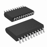
ISL6754AAZA Intersil, ISL6754AAZA Datasheet - Page 7

ISL6754AAZA
Manufacturer Part Number
ISL6754AAZA
Description
IC CTRLR PWM FULL-BRDG 20-QSOP
Manufacturer
Intersil
Datasheet
1.ISL6754AAZA-T.pdf
(19 pages)
Specifications of ISL6754AAZA
Pwm Type
Voltage/Current Mode
Number Of Outputs
6
Frequency - Max
2MHz
Duty Cycle
100%
Voltage - Supply
9 V ~ 16 V
Buck
No
Boost
No
Flyback
No
Inverting
No
Doubler
No
Divider
No
Cuk
No
Isolated
No
Operating Temperature
-40°C ~ 105°C
Package / Case
20-QSOP
Frequency-max
2MHz
Lead Free Status / RoHS Status
Lead free / RoHS Compliant
Available stocks
Company
Part Number
Manufacturer
Quantity
Price
Company:
Part Number:
ISL6754AAZA
Manufacturer:
Intersil
Quantity:
522
Company:
Part Number:
ISL6754AAZA-T
Manufacturer:
Intersil
Quantity:
1 900
Electrical Specifications
NOTES:
SOFT-START
Charging Current
SS Clamp Voltage
SS Discharge Current
Reset Threshold Voltage
OUTPUT
High Level Output Voltage (VOH)
Low Level Output Voltage (VOL)
Rise Time
Fall Time
UVLO Output Voltage Clamp
Output Delay/Advance Range
Delay/Advance Control Voltage Range
V
THERMAL PROTECTION
Thermal Shutdown
Thermal Shutdown Clear
Hysteresis, Internal Protection
4. Limits established by characterization and are not production tested.
5. This is the maximum duty cycle achievable using the specified values of RTD and CT. Larger or smaller maximum duty cycles may be obtained
6. Adjust V
7. When OUTLx is delayed relative to OUTLxN (V
ADJ
OUTLLN/OUTLRN relative to OUTLL/OUTLR
OUTLLN/OUTLRN relative to OUTLL/OUTLR
using other values for these components. See Equations 1 through 3.
time (deadtime) as determined by CT and RTD.
Delay Time
DD
below the UVLO stop threshold prior to setting at 7V.
PARAMETER
7
Recommended operating conditions unless otherwise noted. Refer to “Functional Block Diagram” on page 2
and “Typical Application schematics” beginning on page 3. 9V < V
T
tested at +25°C, unless otherwise specified. Temperature limits established by characterization and are not
production tested. (Continued)
A
= -40°C to +105°C, Typical values are at T
SS = 3V
SS = 2V
T
I
I
C
C
V
V
V
V
OUTLxN Delayed
OUTLxN Advanced
T
T
(Note 4)
(Note 4)
(Note 4)
ADJ
OUT
OUT
A
ADJ
ADJ
ADJ
A
A
DD
OUT
OUT
= +25°C
= +25°C (OUTLx Delayed) (Note 7)
= +25°C (OUTLxN Delayed)
V
V
V
V
V
V
V
V
V
V
< 2.425V), the delay duration as set by V
= 7V, I
ADJ
ADJ
ADJ
ADJ
ADJ
ADJ
ADJ
ADJ
ADJ
ADJ
= -10mA, V
= 10mA, VOL - GND
= 2.50V
< 2.425V
> 2.575V
= 220pF, V
= 220pF, V
= 0
= 0.5V
= 1.0V
= 1.5V
= 2.0V
= V
= V
= V
= V
= V
LOAD
TEST CONDITIONS
REF
REF
REF
REF
REF
ISL6754
DD
DD
DD
= 1mA (Note 6)
- 0.5V
- 1.0V
- 1.5V
- 2.0V
- VOH
= 15V (Note 4)
= 15V (Note 4)
A
= +25°C; Parameters with MIN and/or MAX limits are 100%
ADJ
4.410
2.575
should not exceed 90% of the CT discharge
MIN
0.23
DD
-60
-40
10
40
0
-
-
-
-
-
-
-
-
-
-
-
-
-
-
-
-
-
-
-
< 20V, RTD = 10.0kΩ, CT = 470pF,
4.500
TYP
0.27
300
105
300
100
140
125
110
-70
0.5
0.5
90
70
55
50
68
55
48
15
2
-
-
-
-
-
-
4.590
5.000
2.425
MAX
0.33
1.25
-300
200
150
300
-80
1.0
1.0
-
-
-
-
-
-
-
-
-
-
-
-
-
-
-
September 29, 2008
UNITS
FN6754.1
mA
μA
°C
°C
°C
ns
ns
ns
ns
ns
ns
ns
ns
ns
ns
ns
ns
ns
ns
ns
V
V
V
V
V
V
V


