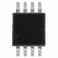
L6926 STMicroelectronics, L6926 Datasheet - Page 8

L6926
Manufacturer Part Number
L6926
Description
IC REG HE SYNC STEP DOWN 8-MSOP
Manufacturer
STMicroelectronics
Type
Step-Down (Buck)r
Specifications of L6926
Internal Switch(s)
Yes
Synchronous Rectifier
No
Number Of Outputs
1
Voltage - Output
0.6 ~ 5.5 V
Current - Output
800mA
Frequency - Switching
600kHz
Voltage - Input
2 ~ 5.5 V
Operating Temperature
-40°C ~ 150°C
Mounting Type
Surface Mount
Package / Case
8-MSOP, Micro8™, 8-uMAX, 8-uSOP,
Power - Output
450mW
Mounting Style
SMD/SMT
High Efficiency
up to 95%
Low Drop-out Operation
up to 100% duty cycle
For Use With
497-4737 - BOARD EVAL L6926 STEP DOWN REG
Lead Free Status / RoHS Status
Lead free / RoHS Compliant
Available stocks
Company
Part Number
Manufacturer
Quantity
Price
Company:
Part Number:
L6926
Manufacturer:
NAIS
Quantity:
21 562
Part Number:
L6926
Manufacturer:
ST
Quantity:
20 000
Part Number:
L6926013TR
Manufacturer:
ST
Quantity:
20 000
Part Number:
L6926D
Manufacturer:
ST
Quantity:
20 000
Company:
Part Number:
L6926Q1TR
Manufacturer:
ST
Quantity:
5 857
Operation description
4.1.1
4.1.2
4.1.3
4.2
8/16
Low consumption mode
In this mode of operation, at light load, the device operates discontinuously based on the
COMP pin voltage, in order to keep the efficiency very high also in these conditions. While
the device is not switching the load discharges the output capacitor and the output voltage
goes down. When the feedback voltage goes lower than the internal reference, the COMP
pin voltage increases and when an internal threshold is reached, the device starts to switch.
In these conditions the peak current limit is set approximately in the range of 200 mA - 400
mA, depending on the slope compensation (see related section).
Once the device starts to switch the output capacitor is recharged. The feedback pin
increases and, when it reaches a value slightly higher than the reference voltage, the output
of the error amplifier goes down until a clamp is activated. At this point, the device stops to
switch. In this phase, most of the internal circuitries are off, so reducing the device
consumption down to a typical value of 25 µA.
Low noise mode
If for noise reasons, the very low frequencies of the low consumption mode are undesirable,
the low noise mode can be selected. In low noise mode, the efficiency is a little bit lower
compared with the low consumption mode in very light load conditions but for medium-high
load currents the efficiency values are very similar.
Basically, the device switches with its internal free running frequency of 600 kHz. Obviously,
in very light load conditions, the device could skip some cycles in order to keep the output
voltage in regulation.
Synchronization
The device can also be synchronized with an external signal from 500 kHz up to 1.4 MHz.
In this case the low noise mode is automatically selected. The device will eventually skip
some cycles in very light load conditions.
The internal synchronization circuit is inhibited in short-circuit and overvoltage conditions in
order to keep the protections effective (see relative sections).
Short circuit protection
During the device operation, the inductor current increases during the high side turn ON
phase and decrease during the high side turn off phase based on the following equations:
Equation 1
Equation 2
In strong overcurrent or short-circuit conditions the V
case ΔI
ON
increases and ΔI
OFF
Doc ID 9302 Rev 9
decreases. When the inductor peak current reaches the
ΔI
ΔI
ON
OFF
=
(
---------------------------------- T
=
V
IN
(
------------------ - T
V
–
OUT
L
L
V
OUT
)
⋅
)
OUT
OFF
⋅
ON
can be very close to zero. In this
L6926


