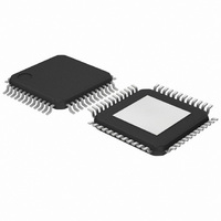
TZA1038HW,118 NXP Semiconductors, TZA1038HW,118 Datasheet - Page 11

TZA1038HW,118
Manufacturer Part Number
TZA1038HW,118
Description
IC DVD SIGNAL PROC 48-HTQFP
Manufacturer
NXP Semiconductors
Datasheet
1.TZA1038HW118.pdf
(45 pages)
Specifications of TZA1038HW,118
Applications
*
Mounting Type
Surface Mount
Package / Case
48-TQFP Exposed Pad, 48-eTQFP, 48-HTQFP, 48-VQFP
Lead Free Status / RoHS Status
Lead free / RoHS Compliant
Other names
935273843118
TZA1038HW-T
TZA1038HW-T
TZA1038HW-T
TZA1038HW-T
Available stocks
Company
Part Number
Manufacturer
Quantity
Price
Company:
Part Number:
TZA1038HW,118
Manufacturer:
NXP Semiconductors
Quantity:
10 000
Philips Semiconductors
7.2
The photodiode configurations and naming conventions
are shown in Figs 4 and 5.
7.2.1
A block diagram of the servo signal path is shown in Fig.6.
In general, the servo signal path comprises:
Servo output signals OA to OD, S1 and S2 are unipolar
current signals which represent the low-pass filtered
photodiode signals. In DPD radial tracking, the S1 and S2
signals are the equivalent of the satellite signals commonly
found in traditional CD systems.
The servo output signals OA to OD, S1 and S2 are set to
3-state if bit RFonly = 1 (register 13, bit 11).
2003 Sep 03
handbook, halfpage
A voltage-to-current converter with programmable offset
voltage source V
A 4-bit DAC for each of the six channels to compensate
for offset per channel
A variable gain stage to adapt the signal level to the
specific pick-up and disc properties
Low-pass filtering and output stage for the photodiode
current signals
Error output stage in the radial data path for fast track
counting.
High speed advanced analog DVD signal
processor and laser supply
Data = A + B + C + D
Push-pull = (A + B)
Focus = (A + C)
DPD2 = phase (A + B, C + D)
DPD4 = phase (A,D) + phase (C,B)
Servo signal processing
S
Fig.4 Astigmatic diode configuration.
ERVO SIGNAL PATH SET
A
D
(B + D)
LFOFFS
(C + D)
B
C
that is common to all inputs
-
UP
tangential direction
left
right
MGW553
11
7.2.2
Focus information is reflected in the four outputs
OA to OD. Gain and offset can be programmed.
For optical pick-ups where only channels B and C are
used for focus, channels A and D can be switched off
(bit Focus_mode = 0).
For initial alignment, a copy of the output currents can be
made available on pin OCENTRAL.
7.2.3
Radial information can be obtained from the two output
signals S1 and S2, and the gain and offset can be
programmed. The TZA1038HW provides differential
phase detection, push-pull and three-beam push-pull for
radial tracking. The signal FTC is made available for fast
track counting and is primarily the voltage error signal
derived from signals S1 or S2.
The polarity of the radial loop can be reversed via the serial
control bus (RAD_pol).
handbook, halfpage
Data = A + B + C + D
Push-pull = A
Focus = C
DPD2 = phase (A, D)
DPD4 not applicable
F
R
OCUS SERVO
ADIAL SERVO
Fig.5 Foucault diode configuration.
A
B
D
B
C
D
left
right
TZA1038HW
tangential direction
Product specification
MGW554


