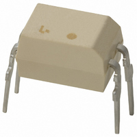
TLP620(F,T) Toshiba, TLP620(F,T) Datasheet - Page 30

TLP620(F,T)
Manufacturer Part Number
TLP620(F,T)
Description
PHOTOCPLR AC IN TRANS-OUT 4-DIP
Manufacturer
Toshiba
Specifications of TLP620(F,T)
Number Of Channels
1
Input Type
AC, DC
Voltage - Isolation
5000Vrms
Current Transfer Ratio (min)
50% @ ±5mA
Current Transfer Ratio (max)
600% @ ±5mA
Voltage - Output
55V
Current - Output / Channel
50mA
Current - Dc Forward (if)
60mA
Vce Saturation (max)
400mV
Output Type
Transistor
Mounting Type
Through Hole
Package / Case
4-DIP (0.300", 7.62mm)
Output Device
Transistor
Number Of Elements
1
Forward Voltage
1.3V
Forward Current
60mA
Collector-emitter Voltage
55V
Package Type
PDIP
Collector Current (dc) (max)
50mA
Isolation Voltage
5000Vrms
Power Dissipation
250mW
Current Transfer Ratio
600%
Pin Count
4
Mounting
Through Hole
Operating Temp Range
-25C to 85C
Operating Temperature Classification
Commercial
Maximum Collector Emitter Voltage
55 V
Maximum Collector Emitter Saturation Voltage
0.4 V
Maximum Forward Diode Voltage
1.3 V
Maximum Collector Current
50 mA
Maximum Power Dissipation
250 mW
Maximum Operating Temperature
+ 100 C
Minimum Operating Temperature
- 55 C
Maximum Fall Time
3 us
Maximum Input Diode Current
60 mA
Maximum Rise Time
2 us
Lead Free Status / RoHS Status
Lead free / RoHS Compliant
Other names
TLP620F
4
MOSFET-Output Photorelays, 2-Form-A in a 2.54SOP8 Package
MOSFET-Output Photorelays, 1-Form-A in a DIP4 Package
*
Note 1: The EN60747-5-2 safety standard for compact packages is different from that for standard DIP packages.
Note 2: BSI and IEC: : Approved (supplementary or basic insulation)
Under development. Specifications subject to change without notice. For the latest information, please contact your nearest Toshiba sales representative.
TLP200D
TLP202A
TLP202G
TLP206A
TLP206G
TLP206GA
TLP209D
TLP220A*
TLP220D*
TLP220G*
TLP220GA*
TLP220J*
TLP221A*
TLP222A
TLP222G
TLP224G
TLP224GA
TLP227A
TLP227G
TLP227GA
TLP225A
Part Number
Part Number
Since the mini-flat package is a compact package, please contact your nearest Toshiba sales representative for more details.
TÜV and VDE: : Approved
For the latest information, please contact your nearest Toshiba sales representative.
Selection Guide
EN 60065- and IEC 60065-approved, EN 60950- and IEC 60950-approved
Pin Configuration
Pin Configuration
EN 60747-5-2-approved with option V4 or D4
8
1
4
1
4
1
7
2
6
3
3
2
3
2
5
4
: Design which meets safety standard/approval pending as of January 2011
DIP4
General-purpose
Reinforced insulation
DIP4
General-purpose
Reinforced insulation
DIP4
General-purpose
Reinforced insulation
DIP4
General-purpose
Reinforced insulation
DIP4
General-purpose
Reinforced insulation
DIP4
General-purpose
Reinforced insulation
DIP4
C
DIP4
C
DIP4
Current-limiting function
Limit current: 150 to 300 mA
DIP4
Current-limiting function
Limit current: 150 to 300 mA
DIP4
C
DIP4
SEMKO-approved
C
DIP4
SEMKO-approved
DIP4
Designed for DC output modules
2.54SOP8
Lead pitch: 2.54 mm
Dual-channel version of the TLP176D
2.54SOP8
Lead pitch: 2.54 mm
Dual-channel version of the TLP172A
2.54SOP8
Lead pitch: 2.54 mm
Dual-channel version of the TLP172G
2.54SOP8
Lead pitch: 2.54 mm
Dual-channel version of the TLP176A
2.54SOP8
Lead pitch: 2.54 mm
Dual-channel version of the TLP176G
2.54SOP8
Lead pitch: 2.54 mm
Dual-channel version of the TLP176GA
2.54SOP8
Lead pitch: 2.54 mm
Dual-channel version of the TLP179D
OFF
OFF
OFF
OFF
: 130 pF (typ.)
: 30 pF (typ.)
: 130 pF (typ.)
: 40 pF (typ.)
SEMKO-approved
For modems
SEMKO-approved
Features
Features
: Approved (reinforced insulation)
(Max)
(Max)
3
3
3
3
3
3
3
2
2
2
2
2
2
3
3
3
3
3
3
3
5
I
I
FT
mA
mA
mA
mA
mA
mA
mA
FT
mA
mA
mA
mA
mA
mA
mA
mA
mA
mA
mA
mA
mA
mA
30
0.2
1.1
50
35
35
50
50
35
60
50
35
35
35
35
8
2
2
2
8
2
2
R
R
Ω
Ω
Ω
Ω
Ω
Ω
Ω
Ω
Ω
Ω
Ω
ON
ON
Ω
Ω
Ω
Ω
Ω
Ω
Ω
Ω
Ω
Ω
(Max)
(Max)
10
5
5
5
5
5
5
5
5
5
5
5
5
5
5
5
5
5
5
5
5
@I
@I
: Design which meets safety standard/approval pending as of January 2011
mA
mA
mA
mA
mA
mA
mA
mA
mA
mA
mA
mA
mA
mA
mA
mA
mA
mA
mA
mA
mA
F
F
±0.25
±0.12
±0.09
0.11
0.12
0.12
0.05
±0.5
±0.1
±1.5
0.12
0.12
0.12
0.12
0.12
(Max)
(Max)
0.2
0.4
0.4
0.5
0.5
0.5
I
I
ON
ON
A
A
A
A
A
A
A
A
A
A
A
A
A
A
A
A
A
A
A
A
A
200
350
400
600
350
350
400
350
400
200
350
350
400
200
V
V
60
60
60
60
60
60
60
OFF
OFF
V
V
V
V
V
V
V
V
V
V
V
V
V
V
V
V
V
V
V
V
V
Vrms
Vrms
Vrms
Vrms
Vrms
Vrms
Vrms
5000
Vrms
5000
Vrms
5000
Vrms
5000
Vrms
5000
Vrms
5000
Vrms
2500
Vrms
2500
Vrms
2500
Vrms
2500
Vrms
2500
Vrms
2500
Vrms
2500
Vrms
2500
Vrms
1500
1500
1500
1500
1500
1500
1500
BVs
BVs
UL/cUL TÜV
UL/cUL TÜV
/
/
/
/
/
/
/ –
/ –
/ –
/ –
/ –
/ –
/ –
/
/
/
/
/
/
/ –
/ –
Safety Standards
Safety Standards
VDE
VDE
(1)
BSI
BSI
(2)
(2)
IEC
IEC


