TLP620(F,T) Toshiba, TLP620(F,T) Datasheet - Page 67
TLP620(F,T)
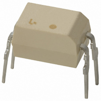
Manufacturer Part Number
TLP620(F,T)
Description
PHOTOCPLR AC IN TRANS-OUT 4-DIP
Manufacturer
Toshiba
Specifications of TLP620(F,T)
Number Of Channels
1
Input Type
AC, DC
Voltage - Isolation
5000Vrms
Current Transfer Ratio (min)
50% @ ±5mA
Current Transfer Ratio (max)
600% @ ±5mA
Voltage - Output
55V
Current - Output / Channel
50mA
Current - Dc Forward (if)
60mA
Vce Saturation (max)
400mV
Output Type
Transistor
Mounting Type
Through Hole
Package / Case
4-DIP (0.300", 7.62mm)
Output Device
Transistor
Number Of Elements
1
Forward Voltage
1.3V
Forward Current
60mA
Collector-emitter Voltage
55V
Package Type
PDIP
Collector Current (dc) (max)
50mA
Isolation Voltage
5000Vrms
Power Dissipation
250mW
Current Transfer Ratio
600%
Pin Count
4
Mounting
Through Hole
Operating Temp Range
-25C to 85C
Operating Temperature Classification
Commercial
Maximum Collector Emitter Voltage
55 V
Maximum Collector Emitter Saturation Voltage
0.4 V
Maximum Forward Diode Voltage
1.3 V
Maximum Collector Current
50 mA
Maximum Power Dissipation
250 mW
Maximum Operating Temperature
+ 100 C
Minimum Operating Temperature
- 55 C
Maximum Fall Time
3 us
Maximum Input Diode Current
60 mA
Maximum Rise Time
2 us
Lead Free Status / RoHS Status
Lead free / RoHS Compliant
Other names
TLP620F


11
1
High Speed
Low Input Current Drive
No Pull-up Resistor Required
High V
Digital Interface Applications
5 V
5 V
5 V
5 V
CC
V
Photocoupler Application Circuit Examples
V
V
V
CC
CC
CC
CC
Tolerance
15 kΩ
2 kΩ
120 pF
LSTTL
LSTTL
CMOS
1.1 kΩ
4.7 kΩ
3 mA
7.5 mA
LSTTL
390 Ω
0.5 mA
1.6 mA
TLP118, TLP2601
TLP2200
TLP558
TLP553
V
V
V
CC
CC
CC
510 kΩ
0.1 μF
0.1 μF
V
V
R
CC
CC
L
LSTTL
CMOS
0.1 μF
= 5 V
= 20 V R
1 kΩ
6.8 kΩ
R
V
V
LSTTL
LSTTL
CC
CC
L
L
5 V
= 3 kΩ
= 12 kΩ
67
V
V
CC
CC
5 V
5 V
The TLP2601 allows high-speed data
transmission at up to approximately 5 MHz.
Data rate of left-side circuit
The high-CTR (current transfer ratio) TLP553
allows operation with low input current (0.5 mA)
and direct driving with a CMOS signal.
Data rate of left-side circuit
When the TLP2200 with a 3-state output is used,
the next-stage logic gate can be actuated
without using a pull-up resistor.
Data rate of left-side circuit
By using the TLP558 which tolerates V
20 V, CMOS logic gates and other components
can be driven without design restrictions on V
Data rate of left-side circuit
f (typ.): 5 Mbit/s (duty cycle ≅ 1/2)
f (typ.): 50 kbit/s (duty cycle ≅ 1/2)
f (typ.): 1 Mbit/s (duty cycle ≅ 1/2)
f (typ.): 1 Mbit/s (duty cycle ≅ 1/2)
CC
up to
CC
.
Related parts for TLP620(F,T)
Image
Part Number
Description
Manufacturer
Datasheet
Request
R

Part Number:
Description:
PHOTOCPLR DL AC IN TRANSOUT 8DIP
Manufacturer:
Toshiba
Datasheet:

Part Number:
Description:
Manufacturer:
TOSHIBA Semiconductor CORPORATION
Datasheet:

Part Number:
Description:
PHOTOCPLR QD AC IN TRANOUT 16DIP
Manufacturer:
Toshiba
Datasheet: