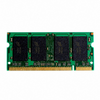
MT16HTS25664HY-53EA1 Micron Technology Inc, MT16HTS25664HY-53EA1 Datasheet

MT16HTS25664HY-53EA1
Specifications of MT16HTS25664HY-53EA1
Related parts for MT16HTS25664HY-53EA1
MT16HTS25664HY-53EA1 Summary of contents
Page 1
DDR2 SDRAM SODIMM MT16HTS25664H – 2GB For component specifications, refer to Micron’s Web site: Features • 200-pin, small outline, dual in-line memory module (SODIMM) • Fast data transfer rates: PC2-3200, PC2-4200, or PC2- 5300 • 2GB (256 Meg x 64) ...
Page 2
... Part Number Density MT16HTS25664HY-667__ 2GB MT16HTS25664HY-53E__ 2GB MT16HTS25664HY-40E__ 2GB Notes: 1. All part numbers end with a two-place code (not shown), designating component and PCB revisions. Consult factory for current revision codes. Example: MT16HTF12864HY-40EA1. PDF: 09005aef821e5bf3/Source: 09005aef82198d54 HTS16C256x64H.fm - Rev. A 4/06 EN 2GB: (x64, DR) 200-Pin DDR2 SDRAM SODIMM ...
Page 3
Module Pin Assignments and Descriptions Table 4: Pin Assignment 200-Pin SODIMM Front Pin Symbol Pin Symbol Pin Symbol Pin Symbol Pin Symbol Pin Symbol Pin Symbol Pin Symbol DQS2 101 REF 103 SS ...
Page 4
Table 5: Pin Descriptions Pin numbers may not correlate with symbols; refer to Pin Assignment tables on page 3 for more information Pin Numbers 114, 119 ODT0, ODT1 30, 32, 164, 166 CK0, CK0# CK1, CK1# 79, 80 CKE0, CKE1 ...
Page 5
Table 5: Pin Descriptions Pin numbers may not correlate with symbols; refer to Pin Assignment tables on page 3 for more information Pin Numbers 197 198, 200 14, 16, 17, 19, 20, DQ0–DQ63 22, 23, 25, ...
Page 6
... Functional Block Diagram Unless otherwise noted, resistor values are 22Ω. Micron module part numbers are explained in the Module Part Numbering Guide a numbering.html. Modules use the following DDR2 SDRAM devices: MT47H128M8BT (1GB). Component specifications are available at: ddr2sdram. Figure 3: Functional Block Diagram 3Ω ...
Page 7
... READs and by the memory controller during WRITEs. DQS is edge- aligned with data for READs and center-aligned with data for WRITEs. DDR2 SDRAM modules operate from a differential clock (CK and CK#); the crossing of CK going HIGH and CK# going LOW will be referred to as the positive edge of CK. ...
Page 8
... Simulations can then render a considerably more accurate result. JEDEC modules are now designed by using simula- tions to close timing budgets. PDF: 09005aef821e5bf3/Source: 09005aef82198d54 HTS16C256x64H ...
Page 9
Table 7: DDR2 I Specifications and Conditions – 2GB DD Values shown for DDR2 SDRAM components only Parameter/Condition Operating one bank active-precharge current RAS = RAS MIN (I ); CKE is HIGH HIGH between ...
Page 10
AC Timing and Operating Conditions Recommended AC operating conditions are given in the DDR2 component data sheets, available at www.micron.com/products/ddr2sdram. Module speed grades correlate with component speed grades as shown in the following table: Table 8: Module and Component Speed ...
Page 11
Figure 4: Data Validity SCL SDA Figure 5: Definition of Start and Stop SCL SDA Figure 6: Acknowledge Response From Receiver SCL from Master Data Output from Transmitter Data Output from Receiver PDF: 09005aef821e5bf3/Source: 09005aef82198d54 HTS16C256x64H.fm - Rev. A 4/06 ...
Page 12
Table 9: EEPROM Device Select Code The most significant bit (b7) is sent first Select Code Memory area select code (two arrays) Protection register select code Table 10: EEPROM Operating Modes Mode Current address read Random address read Sequential read ...
Page 13
Table 11: Serial Presence-Detect EEPROM DC Operating Conditions All voltages referenced to V Parameter/Condition Supply voltage Input high voltage: Logic 1; All inputs Inputl low voltage: Logic 0; All inputs Output low voltage 3mA OUT Input leakage current: ...
Page 14
Table 13: Serial Presence-Detect Matrix “1”/“0”: Serial Data, “driven to HIGH”/“driven to LOW”; table notes located on page 15 Byte Description 0 Number of SPD bytes used by Micron 1 Total number of bytes in SPD device 2 Fundamental memory ...
Page 15
Table 13: Serial Presence-Detect Matrix “1”/“0”: Serial Data, “driven to HIGH”/“driven to LOW”; table notes located on page 15 Byte Description 33 Address and command hold time, 34 Data/ Data mask input setup time, 35 Data/ Data mask input hold ...
Page 16
Module Dimensions Figure 8: 200-pin DDR2 SODIMM Module Dimensions 0.079 (2.00) R (2X) U1 0.071 (1.80) (2X) 0.236 (6.00) 0.100 (2.55) 0.039 (0.99) 0.079 (2.00) U6 PIN 200 Notes: 1. All dimensions are in inches (millimeters); MAX/MIN or TYP where ...


