AFBR-720XPDZ Avago Technologies US Inc., AFBR-720XPDZ Datasheet - Page 11
AFBR-720XPDZ
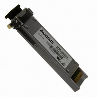
Manufacturer Part Number
AFBR-720XPDZ
Description
TXRX OPT XFP 10GB/S 850NM
Manufacturer
Avago Technologies US Inc.
Datasheet
1.AFBR-720XPDZ.pdf
(15 pages)
Specifications of AFBR-720XPDZ
Wavelength
850nm
Data Rate
10Gbps
Applications
Networking
Voltage - Supply
3.3V
Connector Type
XFP
Mounting Type
Through Hole
Product
Transceiver
Maximum Rise Time
0.024 ns (Min)
Maximum Fall Time
0.024 ns (Min)
Operating Supply Voltage
3.135 V to 3.465 V
Maximum Operating Temperature
+ 70 C
Minimum Operating Temperature
0 C
Package / Case
XFP
Rohs Compliant
Yes
Data Rate Max
10.3125Gbps
Supply Voltage
3.3V
Wavelength Typ
850nm
Peak Reflow Compatible (260 C)
Yes
Leaded Process Compatible
Yes
Lead Free Status / RoHS Status
Lead free / RoHS Compliant
Lead Free Status / RoHS Status
Lead free / RoHS Compliant, Lead free / RoHS Compliant
Other names
516-1996
Available stocks
Company
Part Number
Manufacturer
Quantity
Price
Company:

Part Number:
AFBR-720XPDZ
Manufacturer:
Avago Technologies US Inc.
Quantity:
135


Digital Diagnostic Interface and Serial Identification
The 2-wire serial in��erface is explici��ly defined in ��he ����
�S� Rev 4.0. 2-wire ��iming specifica��ions and ��he s��ruc-
��ure of ��he memory map are per ���� �S� Rev 2.0. The
normal 256 By��e I2C address space is divided in��o lower
and upper blocks of 28 By��es. The lower block of 28
By��es is always direc��ly available and is used for diagnos-
��ic informa��ion providing ��he oppor��uni��y for ��redic��ive
�ailure Iden��ifica��ion, Compliance ��redic��ion, �aul�� Isola-
��ion and Componen�� �oni��oring. The upper address
space ��ables are used for less frequen��ly accessed func-
��ions such as serial ID, user wri��eable EE��RO�, reserved
EE��RO� and diagnos��ics and con��rol spaces for fu��ure
s��andards defini��ion, as well as �vago Technologies-spe-
cific func��ions.
Predictive Failure Identification
The diagnos��ic informa��ion allows ��he hos�� sys��em ��o
iden��ify po��en��ial link problems. Once iden��ified, a “fail
over” ��echnique can be used ��o isola��e and replace sus-
pec�� devices before sys��em up��ime is impac��ed.
Compliance Prediction
The real-��ime diagnos��ic parame��ers can be moni��ored
��o aler�� ��he sys��em when opera��ing limi��s are exceeded
and compliance canno�� be ensured. �s an example, ��he
real ��ime average receive op��ical power can be used ��o
assess ��he compliance of ��he cable plan�� and remo��e
��ransmi����er.
Fault Isolation
The diagnos��ic informa��ion can allow ��he hos�� ��o pin-
poin�� ��he loca��ion of a link problem and accelera��e sys-
��em servicing and minimize down��ime.
Component Monitoring
�s par�� of hos�� sys��em qualifica��ion and verifica��ion,
real ��ime ��ransceiver diagnos��ic informa��ion can be
combined wi��h sys��em level moni��oring ��o ensure per-
formance and opera��ing environmen�� are mee��ing ap-
plica��ion requiremen��s.
Transceiver Internal Temperature
Tempera��ure is measured on ��he ��BR-720���DZ us-
ing sensing circui��ry moun��ed on ��he in��ernal ��CB.
The measured ��empera��ure will generally be cooler
��han laser junc��ion and warmer ��han ���� case and can
be indirec��ly correla��ed ��o ���� case or laser junc��ion
��empera��ure using ��hermal resis��ance and capaci��ance
modeling. This measuremen�� can be used ��o observe
drif��s in ��hermal opera��ing poin�� or ��o de��ec�� ex��reme
��empera��ure fluc��ua��ions such as a failure in ��he sys��em
��hermal con��rol. �or more informa��ion on correla��ing
in��ernal ��empera��ure ��o case or laser junc��ion con��ac��
�vago Technologies.
Transmitter Laser DC Bias Current
Laser bias curren�� is measured using sensing circui��ry
loca��ed on ��he ��ransmi����er laser driver IC. Normal varia-
��ions in laser bias curren�� are expec��ed ��o accommoda��e
��he impac�� of changing ��ransceiver ��empera��ure and
supply vol��age opera��ing poin��s. The ��BR-720���DZ
uses a closed loop laser bias feedback circui�� ��o main��ain
cons��an�� op��ical power. This circui�� compensa��es for nor-
mal laser parame��ric varia��ions in quan��um efficiency,
forward vol��age and lasing ��hreshold due ��o changing
��ransceiver opera��ing poin��s.
Transmitted Average Optical Output Power
Varia��ions in average op��ical power are no�� expec��ed
under normal opera��ion because ��he ��BR-720���DZ
uses a closed loop laser bias feedback circui�� ��o main-
��ain cons��an�� op��ical power. This circui�� compensa��es
for normal laser parame��ric varia��ions due ��o changing
��ransceiver opera��ing poin��s. Only under ex��reme laser
bias condi��ions will significan�� drif��ing in ��ransmi����ed
average op��ical power be observable. Therefore i�� is rec-
ommended Tx average op��ical power be used for faul��
isola��ion, ra��her ��han predic��ive failure purposes.
Received Average Optical Input Power
Received average op��ical power measuremen��s are a
valuable asse�� for ins��allers ��o verify cable plan�� compli-
ance. Drif��s in average power can be observed from ��he
cable plan�� and remo��e ��ransmi����er for po��en��ial predic-
��ive failure use. Received average op��ical power can be
used for faul�� isola��ion.
Auxilliary Monitors
In addi��ion ��o ��he parame��ers men��ioned above, 3.3V
Supply Vol��age (�U�) is also repor��ed as auxilliary pa-
rame��er .
Related parts for AFBR-720XPDZ
Image
Part Number
Description
Manufacturer
Datasheet
Request
R

Part Number:
Description:
TXRX OPT OC3 MTRJ SFF 2X5DIP
Manufacturer:
Avago Technologies US Inc.
Datasheet:

Part Number:
Description:
TXRX ETHERNET 125MBD MMF 2X5
Manufacturer:
Avago Technologies US Inc.
Datasheet:

Part Number:
Description:
TXRX OPT SFP DGTL 850NM IND
Manufacturer:
Avago Technologies US Inc.
Datasheet:

Part Number:
Description:
650nm FE Transceiver Eval Kit
Manufacturer:
Avago Technologies US Inc.
Datasheet:

Part Number:
Description:
TXRX OPT SFF 4/2/1GBD 2X7
Manufacturer:
Avago Technologies US Inc.
Datasheet:

Part Number:
Description:
TXRX OPT SFP 4/2/1GBD 850NM
Manufacturer:
Avago Technologies US Inc.
Datasheet:

Part Number:
Description:
TXRX OPT 1X9 100MBPS ST EXT TEMP
Manufacturer:
Avago Technologies US Inc.
Datasheet:

Part Number:
Description:
TXRX OPT 1X9 100MBPS SC EXT TEMP
Manufacturer:
Avago Technologies US Inc.
Datasheet:

Part Number:
Description:
TXRX OPT 1X9 100MBPS DUPLEX SC
Manufacturer:
Avago Technologies US Inc.
Datasheet:

Part Number:
Description:
TXRX OPT 1X9 100MBPS DUPLEX ST
Manufacturer:
Avago Technologies US Inc.
Datasheet:

Part Number:
Description:
OPTOCOUPLER GATE DRV 2A 16-SOIC
Manufacturer:
Avago Technologies US Inc.
Datasheet:
Part Number:
Description:
OPTOCOUPLER 2CH 2.5A 16-SOIC
Manufacturer:
Avago Technologies US Inc.
Datasheet:

Part Number:
Description:
OPTOCOUPLER GATE DRV 0.4A 16SOIC
Manufacturer:
Avago Technologies US Inc.
Datasheet:

Part Number:
Description:
OPTOCOUPLER 2.0A 250KHZ 8-DIP
Manufacturer:
Avago Technologies US Inc.
Datasheet:

Part Number:
Description:
OPTOCOUPLER 2.0A 250KHZ GW 8-SMD
Manufacturer:
Avago Technologies US Inc.
Datasheet: