AFBR-720XPDZ Avago Technologies US Inc., AFBR-720XPDZ Datasheet - Page 3
AFBR-720XPDZ
Manufacturer Part Number
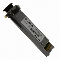
AFBR-720XPDZ
Description
TXRX OPT XFP 10GB/S 850NM
Manufacturer
Avago Technologies US Inc.
Datasheet
1.AFBR-720XPDZ.pdf
(15 pages)
Specifications of AFBR-720XPDZ
Wavelength
850nm
Data Rate
10Gbps
Applications
Networking
Voltage - Supply
3.3V
Connector Type
XFP
Mounting Type
Through Hole
Product
Transceiver
Maximum Rise Time
0.024 ns (Min)
Maximum Fall Time
0.024 ns (Min)
Operating Supply Voltage
3.135 V to 3.465 V
Maximum Operating Temperature
+ 70 C
Minimum Operating Temperature
0 C
Package / Case
XFP
Rohs Compliant
Yes
Data Rate Max
10.3125Gbps
Supply Voltage
3.3V
Wavelength Typ
850nm
Peak Reflow Compatible (260 C)
Yes
Leaded Process Compatible
Yes
Lead Free Status / RoHS Status
Lead free / RoHS Compliant
Lead Free Status / RoHS Status
Lead free / RoHS Compliant, Lead free / RoHS Compliant
Other names
516-1996
Available stocks
Company
Part Number
Manufacturer
Quantity
Price
Company:

Part Number:
AFBR-720XPDZ
Manufacturer:
Avago Technologies US Inc.
Quantity:
135


Receiver Section
The receiver sec��ion includes a ��IN de��ec��or wi��h am-
plifica��ion quan��iza��ion signal condi��ioner circui��s. (see
�igure ) Op��ical connec��ion ��o ��he receiver is provided
via a LC op��ical connec��or.
RX_LOS
The receiver sec��ion con��ains a loss of signal (R�_LOS)
circui�� ��o indica��e when ��he op��ical inpu�� signal power
is insufficien�� for reliable signal de��ec��ion. � high signal
indica��es loss of modula��ed signal, indica��ing link failure
such as a broken fiber or nonfunc��ional remo��e ��rans-
mi����er. R�_LOS can also be moni��ored via ��he ��wo-wire
serial in��erface (by��e 0, bi�� ).
Figure 2. MSA recommended power supply filter
3
Optional
Host +1.8 V
Optional
Host -5.2 V
Optional
Host +5 V
Host +3.3 V
0.1 µF
0.1 µF
0.1 µF
0.1 µF
4.7 µH
4.7 µH
4.7 µH
4.7 µH
GND
22 µF
22 µF
22 µF
22 µF
Host Board
0.1 µF
0.1 µF
0.1 µF
0.1 µF
V
V
V
V
CC
CC
CC
EE
5
5
3
2
XFP Module
Functional Data I/O
�vago Technologies’ ��BR-720���DZ fiber-op��ic ��rans-
ceiver is designed ��o accep�� indus��ry s��andard elec��rical
inpu�� differen��ial signals. The ��ransceiver provides ac-
coupled, in��ernally ��ermina��ed da��a inpu�� and ou��pu��
in��erfaces. Bias resis��ors and coupling capaci��ors have
been included wi��hin ��he module ��o reduce ��he number
of componen��s required on ��he cus��omer’s board.
Electrical Pinout
Figure 3. Host PCB XFP Pinout Top View
TOWARD
ASIC
16
17
18
19
20
21
22
23
24
25
26
27
28
29
30
GND
RD-
RD+
GND
VCC2
P_DOWN/RST
VCC2
GND
REFCLK+
REFCLK-
GND
GND
TD-
TD+
GND
INTERRUPT
GND
RX_LOS
MOD_NR
MOD_ABS
SDA
SCL
VCC3
VCC3
GND
VCC5
TX_DIS
MOD_DESEL
VEE5
GND
15
14
13
12
11
10
9
8
7
6
5
4
3
2
1
TOWARD
BEZEL
Related parts for AFBR-720XPDZ
Image
Part Number
Description
Manufacturer
Datasheet
Request
R

Part Number:
Description:
TXRX OPT OC3 MTRJ SFF 2X5DIP
Manufacturer:
Avago Technologies US Inc.
Datasheet:

Part Number:
Description:
TXRX ETHERNET 125MBD MMF 2X5
Manufacturer:
Avago Technologies US Inc.
Datasheet:

Part Number:
Description:
TXRX OPT SFP DGTL 850NM IND
Manufacturer:
Avago Technologies US Inc.
Datasheet:

Part Number:
Description:
650nm FE Transceiver Eval Kit
Manufacturer:
Avago Technologies US Inc.
Datasheet:

Part Number:
Description:
TXRX OPT SFF 4/2/1GBD 2X7
Manufacturer:
Avago Technologies US Inc.
Datasheet:

Part Number:
Description:
TXRX OPT SFP 4/2/1GBD 850NM
Manufacturer:
Avago Technologies US Inc.
Datasheet:

Part Number:
Description:
TXRX OPT 1X9 100MBPS ST EXT TEMP
Manufacturer:
Avago Technologies US Inc.
Datasheet:

Part Number:
Description:
TXRX OPT 1X9 100MBPS SC EXT TEMP
Manufacturer:
Avago Technologies US Inc.
Datasheet:

Part Number:
Description:
TXRX OPT 1X9 100MBPS DUPLEX SC
Manufacturer:
Avago Technologies US Inc.
Datasheet:

Part Number:
Description:
TXRX OPT 1X9 100MBPS DUPLEX ST
Manufacturer:
Avago Technologies US Inc.
Datasheet:

Part Number:
Description:
OPTOCOUPLER GATE DRV 2A 16-SOIC
Manufacturer:
Avago Technologies US Inc.
Datasheet:
Part Number:
Description:
OPTOCOUPLER 2CH 2.5A 16-SOIC
Manufacturer:
Avago Technologies US Inc.
Datasheet:

Part Number:
Description:
OPTOCOUPLER GATE DRV 0.4A 16SOIC
Manufacturer:
Avago Technologies US Inc.
Datasheet:

Part Number:
Description:
OPTOCOUPLER 2.0A 250KHZ 8-DIP
Manufacturer:
Avago Technologies US Inc.
Datasheet:

Part Number:
Description:
OPTOCOUPLER 2.0A 250KHZ GW 8-SMD
Manufacturer:
Avago Technologies US Inc.
Datasheet: