PCM18XK1 Microchip Technology, PCM18XK1 Datasheet - Page 119
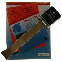
PCM18XK1
Manufacturer Part Number
PCM18XK1
Description
MODULE PROC PIC18F8680,6680,8565
Manufacturer
Microchip Technology
Datasheet
1.PCM18XK1.pdf
(496 pages)
Specifications of PCM18XK1
Accessory Type
Processor Module
Lead Free Status / RoHS Status
Not applicable / Not applicable
For Use With/related Products
ICE2000
For Use With
ICE2000 - EMULATOR MPLAB-ICE 2000 POD
Lead Free Status / Rohs Status
Lead free / RoHS Compliant


9.3
The PIE registers contain the individual enable bits for
the peripheral interrupts. Due to the number of
peripheral interrupt sources, there are three Peripheral
Interrupt Enable registers (PIE1, PIE2 and PIE3).
When the IPEN bit (RCON<7>) is ‘0’, the PEIE bit must
be set to enable any of these peripheral interrupts.
REGISTER 9-7:
2004 Microchip Technology Inc.
PIE Registers
bit 7
bit 6
bit 5
bit 4
bit 3
bit 2
bit 1
bit 0
PIE1: PERIPHERAL INTERRUPT ENABLE REGISTER 1
bit 7
PSPIE: Parallel Slave Port Read/Write Interrupt Enable bit
1 = Enables the PSP read/write interrupt
0 = Disables the PSP read/write interrupt
ADIE: A/D Converter Interrupt Enable bit
1 = Enables the A/D interrupt
0 = Disables the A/D interrupt
RCIE: USART Receive Interrupt Enable bit
1 = Enables the USART receive interrupt
0 = Disables the USART receive interrupt
TXIE: USART Transmit Interrupt Enable bit
1 = Enables the USART transmit interrupt
0 = Disables the USART transmit interrupt
SSPIE: Master Synchronous Serial Port Interrupt Enable bit
1 = Enables the MSSP interrupt
0 = Disables the MSSP interrupt
CCP1IE: Enhanced CCP1 Interrupt Enable bit
1 = Enables the CCP1 interrupt
0 = Disables the CCP1 interrupt
TMR2IE: TMR2 to PR2 Match Interrupt Enable bit
1 = Enables the TMR2 to PR2 match interrupt
0 = Disables the TMR2 to PR2 match interrupt
TMR1IE: TMR1 Overflow Interrupt Enable bit
1 = Enables the TMR1 overflow interrupt
0 = Disables the TMR1 overflow interrupt
Legend:
R = Readable bit
- n = Value at POR
PSPIE
R/W-0
Note 1: Available in Microcontroller mode only.
(1)
R/W-0
ADIE
PIC18F6585/8585/6680/8680
R/W-0
RCIE
W = Writable bit
‘1’ = Bit is set
R/W-0
TXIE
SSPIE
R/W-0
U = Unimplemented bit, read as ‘0’
‘0’ = Bit is cleared
(1)
CCP1IE
R/W-0
x = Bit is unknown
TMR2IE
R/W-0
DS30491C-page 117
TMR1IE
R/W-0
bit 0
Related parts for PCM18XK1
Image
Part Number
Description
Manufacturer
Datasheet
Request
R

Part Number:
Description:
Manufacturer:
Microchip Technology Inc.
Datasheet:
Part Number:
Description:
Manufacturer:
Microchip Technology Inc.
Datasheet:
Part Number:
Description:
Manufacturer:
Microchip Technology Inc.
Datasheet:
Part Number:
Description:
Manufacturer:
Microchip Technology Inc.
Datasheet:
Part Number:
Description:
Manufacturer:
Microchip Technology Inc.
Datasheet:
Part Number:
Description:
Manufacturer:
Microchip Technology Inc.
Datasheet:
Part Number:
Description:
Manufacturer:
Microchip Technology Inc.
Datasheet:
Part Number:
Description:
Manufacturer:
Microchip Technology Inc.
Datasheet: