PCM18XK1 Microchip Technology, PCM18XK1 Datasheet - Page 352
PCM18XK1
Manufacturer Part Number
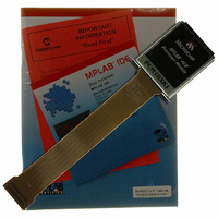
PCM18XK1
Description
MODULE PROC PIC18F8680,6680,8565
Manufacturer
Microchip Technology
Datasheet
1.PCM18XK1.pdf
(496 pages)
Specifications of PCM18XK1
Accessory Type
Processor Module
Lead Free Status / RoHS Status
Not applicable / Not applicable
For Use With/related Products
ICE2000
For Use With
ICE2000 - EMULATOR MPLAB-ICE 2000 POD
Lead Free Status / Rohs Status
Lead free / RoHS Compliant


PIC18F6585/8585/6680/8680
REGISTER 24-5:
REGISTER 24-6:
DS30491C-page 350
bit 7
bit 6-2
bit 1
bit 0
bit 7
bit 6-3
bit 2
bit 1
bit 0
CONFIG3H: CONFIGURATION REGISTER 3 HIGH (BYTE ADDRESS 300005h)
CONFIG4L: CONFIGURATION REGISTER 4 LOW (BYTE ADDRESS 300006h)
MCLRE: MCLR Enable bit
1 = MCLR pin enabled, RG5 input pin disabled
0 = RG5 input enabled, MCLR disabled
Unimplemented: Read as ‘0’
ECCPMX: CCP1 PWM outputs P1B, P1C mux bit (PIC18F8X8X devices only)
1 = P1B, P1C are multiplexed with RE6, RE5
0 = P1B, P1C are multiplexed with RH7, RH6
CCP2MX: CCP2 Mux bit
In Microcontroller mode:
1 = CCP2 input/output is multiplexed with RC1
0 = CCP2 input/output is multiplexed with RE7
In Microprocessor, Microprocessor with Boot Block and Extended Microcontroller modes
(PIC18F8X8X devices only):
1 = CCP2 input/output is multiplexed with RC1
0 = CCP2 input/output is multiplexed with RB3
bit 7
DEBUG: Background Debugger Enable bit
1 = Background debugger disabled. RB6 and RB7 configured as general purpose I/O pins.
0 = Background debugger enabled. RB6 and RB7 are dedicated to in-circuit debug.
Unimplemented: Read as ‘0’
LVP: Low-Voltage ICSP Enable bit
1 = Low-voltage ICSP enabled
0 = Low-voltage ICSP disabled
Unimplemented: Read as ‘0’
STVREN: Stack Full/Underflow Reset Enable bit
1 = Stack full/underflow will cause Reset
0 = Stack full/underflow will not cause Reset
bit 7
Legend:
R = Readable bit
- n = Value when device is unprogrammed
Legend:
R = Readable bit
- n = Value when device is unprogrammed
DEBUG
MCLRE
Note 1: If MCLR is disabled, either disable low-voltage ICSP or hold RB5/PGM low to
R/P-1
R/P-1
2: Reserved for PIC18F6X8X devices; maintain this bit set.
ensure proper entry into ICSP mode.
U-0
U-0
—
—
P = Programmable bit
P = Programmable bit
(1)
U-0
—
U-0
—
U-0
—
U-0
—
U = Unimplemented bit, read as ‘0’
u = Unchanged from programmed state
U = Unimplemented bit, read as ‘0’
u = Unchanged from programmed state
U-0
—
U-0
—
R/P-1
LVP
U-0
—
2004 Microchip Technology Inc.
ECCPMX
R/P-1
U-0
—
(2)
CCP2MX
STVREN
R/P-1
R/P-1
bit 0
bit 0
Related parts for PCM18XK1
Image
Part Number
Description
Manufacturer
Datasheet
Request
R

Part Number:
Description:
Manufacturer:
Microchip Technology Inc.
Datasheet:
Part Number:
Description:
Manufacturer:
Microchip Technology Inc.
Datasheet:
Part Number:
Description:
Manufacturer:
Microchip Technology Inc.
Datasheet:
Part Number:
Description:
Manufacturer:
Microchip Technology Inc.
Datasheet:
Part Number:
Description:
Manufacturer:
Microchip Technology Inc.
Datasheet:
Part Number:
Description:
Manufacturer:
Microchip Technology Inc.
Datasheet:
Part Number:
Description:
Manufacturer:
Microchip Technology Inc.
Datasheet:
Part Number:
Description:
Manufacturer:
Microchip Technology Inc.
Datasheet: