STEVAL-ILL025V1 STMicroelectronics, STEVAL-ILL025V1 Datasheet - Page 11
STEVAL-ILL025V1
Manufacturer Part Number
STEVAL-ILL025V1
Description
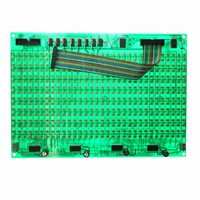
LED MATRIX DISPLAY PANEL
Manufacturer
STMicroelectronics
Datasheets
1.STP16DP05TTR.pdf
(31 pages)
2.STEVAL-ILL025V1.pdf
(30 pages)
3.STEVAL-ILL025V1.pdf
(4 pages)
Specifications of STEVAL-ILL025V1
Design Resources
STEVAL-ILL025V1 BOM STEVAL-ILL025V1 Schematic
Accessory Type
Daughter Board
Description/function
LED Demo System Display Unit
Product
Display Modules
Software
Software Included
For Use With/related Products
*
Lead Free Status / RoHS Status
Lead free / RoHS Compliant
Other names
497-9087
Available stocks
Company
Part Number
Manufacturer
Quantity
Price
Company:

Part Number:
STEVAL-ILL025V1
Manufacturer:
STMicroelectronics
Quantity:
1


UM0767
3.2
●
●
Two control units and one display unit configuration
In this configuration there are two control units and a single display unit. One control unit
should be the master and the second should be the slave. By default, the system comes
with one master and one display panel.
The steps to operate the system in this configuration are listed below:
●
●
●
●
If needed, the display panels can be cascaded in series to create a longer display. To
cascade the display panels connect a 20-pin flat-ribbon cable from the J3 jumper (output) of
the first panel to the J1 jumper (input) of the second panel.
for cascading the display panels. Similarly, connect the FRC cable from the J3 jumper
(output) of the second panel to the J1 jumper (input) of the third panel and so on to create a
longer display. Up to 8 such display panels can be cascaded in series.
●
●
●
Step 12: press Esc on the keyboard to exit the selected mode.
Step 13: once out of the selected mode, the system resumes from step 9.
Step 1: configure one control unit as the master and the second control unit as the
slave, as explained in
Step 2: configure the address of the slave board using the on-board DIP switches, as
explained in
Step 3: connect the PS2 keyboard to the master control unit.
Step 4: connect the display panel to the slave control unit using a 20-pin flat-ribbon
cable. Insert the cable into the 10 x 2 header (Ext.Con) present on the slave at one side
and into the J1 header (input) on the display panel at the other side.
Step 5: connect the master and the slave control unit using a twisted pair cable. Ensure
that RS485+ at master is connected to RS485+ at slave and RS485- at master is
connected to RS485- at slave. Connections are made at the J18 screw type connector.
Figure 7
Step 6: power-up the master control unit, the slave control unit and the display panel
using DC power supplies.
Step 7: the LCD on the master and slave control unit shows “Press “#” to enter
ConfigurationMod”. This is displayed for 4 seconds. If the master and slave boards are
shows the RS485 connection topology.
Section
2.1.1.
Section
Doc ID 16147 Rev 1
2.1.2.
Figure 6
shows the connections
System configuration
11/30
Related parts for STEVAL-ILL025V1
Image
Part Number
Description
Manufacturer
Datasheet
Request
R

Part Number:
Description:
BOARD EVAL FOR MEMS SENSORS
Manufacturer:
STMicroelectronics
Datasheet:

Part Number:
Description:
KIT DEV STARTER ST10F276Z5
Manufacturer:
STMicroelectronics
Datasheet:

Part Number:
Description:
BOARD EVAL HDMI $ VIDEO SWITCH
Manufacturer:
STMicroelectronics
Datasheet:

Part Number:
Description:
BOARD DEMO ACCELEROMETER DIL24
Manufacturer:
STMicroelectronics
Datasheet:

Part Number:
Description:
BOARD STLM75/STDS75/ST72F651
Manufacturer:
STMicroelectronics
Datasheet:

Part Number:
Description:
EVAL BOARD 3AXIS MEMS ACCELLRMTR
Manufacturer:
STMicroelectronics
Datasheet:

Part Number:
Description:
BOARD EVAL 8BIT MICRO + TDE1708
Manufacturer:
STMicroelectronics
Datasheet:

Part Number:
Description:
EVAL BOARD A/D TS4657
Manufacturer:
STMicroelectronics
Datasheet:

Part Number:
Description:
BOARD ADAPTER 20DIP LIS3LV02DL
Manufacturer:
STMicroelectronics
Datasheet:

Part Number:
Description:
BOARD DEMO STM8S207R6/LIS331DLH
Manufacturer:
STMicroelectronics
Datasheet:

Part Number:
Description:
STMicroelectronics [RIPPLE-CARRY BINARY COUNTER/DIVIDERS]
Manufacturer:
STMicroelectronics
Datasheet:
Part Number:
Description:
STMicroelectronics [LIQUID-CRYSTAL DISPLAY DRIVERS]
Manufacturer:
STMicroelectronics
Datasheet:
Part Number:
Description:
BOARD EVAL FOR MEMS SENSORS
Manufacturer:
STMicroelectronics
Datasheet: