DLP-2232M-G DLP Design Inc, DLP-2232M-G Datasheet - Page 22
DLP-2232M-G
Manufacturer Part Number
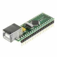
DLP-2232M-G
Description
MODULE USB ADAPTER FOR FT2232D
Manufacturer
DLP Design Inc
Datasheet
1.DLP-2232M-G.pdf
(33 pages)
Specifications of DLP-2232M-G
Main Purpose
Interface, USB 2.0 to UART (RS232) Bridge
Embedded
No
Utilized Ic / Part
FT2232D
Primary Attributes
Full Speed USB to High-Speed UART
Secondary Attributes
Royalty-Free Drivers, 2K EEPROM
Interface Type
USB
Data Bus Width
8 bit
Operating Supply Voltage
4.35 V to 5.25 V
Product
Interface Modules
For Use With/related Products
FT2232D
Lead Free Status / RoHS Status
Lead free / RoHS Compliant
Lead Free Status / RoHS Status
Lead free / RoHS Compliant, Lead free / RoHS Compliant
Other names
813-1000


9.5 Enhanced Asynchronous Bit-Bang Mode
Enhanced Asynchronous Bit-Bang mode is the same as BM-style Bit-Bang mode, except
that the internal RD# and WR# strobes are now brought out of the DLP-2232M-G to
allow external logic to be clocked by accesses to the bit-bang IO bus.
On either or both channels, any data written to the device in the normal manner will be
self clocked onto the data pins (those which have been configured as outputs). Each pin
can be independently set as an input or an output. The baud rate generator controls the
rate at which the data is clocked out.
For the data to change there has to be new data written, and the baud rate clock has to
tick. If no new data is written to the channel, the pins will hold the last value written.
To allow time for the data to be setup and held around the WR# strobe, the baud rate
should be less than 1 MegaBaud.
Enabling
Asynchronous Bit-Bang mode is enabled by the Set Bit Bang Mode command:
Set_USB_Device_BitMode($00,$01) ; to enable it
Set_USB_Device_BitMode($00,$00) ; to reset it
9.6 Synchronous Bit-Bang Mode
With Synchronous Bit-Bang enabled, data will only be sent out by the FT2232D if there
is space in the device for data to come in. This Synchronous Bit-Bang mode will read the
data bus pins first, before it sends out the byte that has just been transmitted. It is
therefore 1 byte behind the output, and so to read the inputs for the byte that you have
just sent, another byte must be sent.
For example:
(1)
Pins start at 0xFF
Send 0x55,0xAA
Pins go to 0x55 and then to 0xAA
DS2232C Version 1.0 © Future Technology Devices Intl. Ltd. 2004 Page 40 of 52FT2232D Dual
USB UART / FIFO I.C.
Data read = 0xFF,0x55
Rev 1.6 (May 2009)
22
DLP-2232M-G DLP Design, Inc.
Related parts for DLP-2232M-G
Image
Part Number
Description
Manufacturer
Datasheet
Request
R

Part Number:
Description:
MODULE USB-TO-TTL PARL FIFO CONV
Manufacturer:
DLP Design Inc
Datasheet:

Part Number:
Description:
KIT DEV DLP LIGHTCOMANDER
Manufacturer:
Logic
Datasheet:

Part Number:
Description:
MODULE DATA-ACQUISITION 8-CH
Manufacturer:
DLP Design Inc
Datasheet:

Part Number:
Description:
MODULE DATA-ACQUISITION 20-CH
Manufacturer:
DLP Design Inc
Datasheet:

Part Number:
Description:
RFID READER/WRITER SNGL-CH OEM
Manufacturer:
DLP Design Inc
Datasheet:

Part Number:
Description:
Interface Modules & Development Tools DLP-245PL PACKAGED w/CCS Compiler
Manufacturer:
DLP Design Inc

Part Number:
Description:
Interface Modules & Development Tools DLP-245PB-G BOARD + CCS Compiler
Manufacturer:
DLP Design Inc
Datasheet:

Part Number:
Description:
Interface Modules & Development Tools DLP-TILT SENSOR ACCEL VIBRATION
Manufacturer:
DLP Design Inc

Part Number:
Description:
MODULE USB-MCU FT245RL W/16F877A
Manufacturer:
DLP Design Inc
Datasheet:

Part Number:
Description:
MODULE USB-TO-FPGA TRAINING TOOL
Manufacturer:
DLP Design Inc
Datasheet:

Part Number:
Description:
MODULE USB-MCU FT232R W/18F2410
Manufacturer:
DLP Design Inc
Datasheet:

Part Number:
Description:
MODULE USB-MCU FT245RL W/SX48
Manufacturer:
DLP Design Inc
Datasheet:

Part Number:
Description:
MODULE USB-MCU FT2232D W/16F877A
Manufacturer:
DLP Design Inc
Datasheet:

Part Number:
Description:
MODULE USB-TO-FPGA SPARTAN3
Manufacturer:
DLP Design Inc
Datasheet:

Part Number:
Description:
MOD USB-MCU FT245RL W/18LF8722
Manufacturer:
DLP Design Inc
Datasheet: