DLP-2232M-G DLP Design Inc, DLP-2232M-G Datasheet - Page 31
DLP-2232M-G
Manufacturer Part Number
DLP-2232M-G
Description
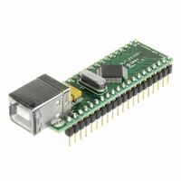
MODULE USB ADAPTER FOR FT2232D
Manufacturer
DLP Design Inc
Datasheet
1.DLP-2232M-G.pdf
(33 pages)
Specifications of DLP-2232M-G
Main Purpose
Interface, USB 2.0 to UART (RS232) Bridge
Embedded
No
Utilized Ic / Part
FT2232D
Primary Attributes
Full Speed USB to High-Speed UART
Secondary Attributes
Royalty-Free Drivers, 2K EEPROM
Interface Type
USB
Data Bus Width
8 bit
Operating Supply Voltage
4.35 V to 5.25 V
Product
Interface Modules
For Use With/related Products
FT2232D
Lead Free Status / RoHS Status
Lead free / RoHS Compliant
Lead Free Status / RoHS Status
Lead free / RoHS Compliant, Lead free / RoHS Compliant
Other names
813-1000


(iv) If the target device is unable to accept the data when it detects the start bit, it should
stop the FSCLK until it can accept the data.
Incoming Fast Serial Data
The external device is allowed to send data into the chip if FSCTS is high. On receipt of
a Zero start bit on FSDI, the module will drop FSCTS on the next positive clock edge.
The data from bits 0 to 7 is then clocked in (LSB first). The next bit determines where
the data will be written. It can go to either channel A or to channel B. A ‘0’ will send it
to channel A, providing channel A is enabled for fast serial mode, otherwise it will go to
channel B. A ‘1’ will send it to channel B, providing channel B is enabled for fast serial
mode, otherwise it will go to channel A. Either channel A, or channel B, or both must be
enabled as fast serial mode or the circuit is disabled.
Figure 35 - Fast Opto-Isolated Serial Data Format - Data input to the DLP-2232M-G
FSCTS
FSCLK
FSDI
0
D0
D1
D2
D3
D4
D5
D6
D7
DEST
Start
Destination
Bit
Bit
Data Bits - LSB first
Notes:
(i) Start Bit is always 0.
(ii) Data is sent LSB first.
(iii) The destination bit (DEST) indicates which channel the data should go to. A ‘0’
means that it should go to channel A, a ‘1’ means that it should go to channel B.
(iv) The target device should check CTS is high before it sends data. CTS goes low after
data bit 0 (D0) and stays low until the chip can accept more data.
Contention
There is a possibility that contention may occur, where the interface goes from being
completely idle to both sending and receiving at the same clock instance. In this case the
chip backs off, and allow the data from the external device to be received.
Data Format
The data format for either direction is:
1) Zero Start Bit
2) Data bit 0
3) Data bit 1
4) Data bit 2
5) Data bit 3
6) Data bit 4
7) Data bit 5
Rev 1.6 (May 2009)
31
DLP-2232M-G DLP Design, Inc.
Related parts for DLP-2232M-G
Image
Part Number
Description
Manufacturer
Datasheet
Request
R

Part Number:
Description:
MODULE USB-TO-TTL PARL FIFO CONV
Manufacturer:
DLP Design Inc
Datasheet:

Part Number:
Description:
KIT DEV DLP LIGHTCOMANDER
Manufacturer:
Logic
Datasheet:

Part Number:
Description:
MODULE DATA-ACQUISITION 8-CH
Manufacturer:
DLP Design Inc
Datasheet:

Part Number:
Description:
MODULE DATA-ACQUISITION 20-CH
Manufacturer:
DLP Design Inc
Datasheet:

Part Number:
Description:
RFID READER/WRITER SNGL-CH OEM
Manufacturer:
DLP Design Inc
Datasheet:

Part Number:
Description:
Interface Modules & Development Tools DLP-245PL PACKAGED w/CCS Compiler
Manufacturer:
DLP Design Inc

Part Number:
Description:
Interface Modules & Development Tools DLP-245PB-G BOARD + CCS Compiler
Manufacturer:
DLP Design Inc
Datasheet:

Part Number:
Description:
Interface Modules & Development Tools DLP-TILT SENSOR ACCEL VIBRATION
Manufacturer:
DLP Design Inc

Part Number:
Description:
MODULE USB-MCU FT245RL W/16F877A
Manufacturer:
DLP Design Inc
Datasheet:

Part Number:
Description:
MODULE USB-TO-FPGA TRAINING TOOL
Manufacturer:
DLP Design Inc
Datasheet:

Part Number:
Description:
MODULE USB-MCU FT232R W/18F2410
Manufacturer:
DLP Design Inc
Datasheet:

Part Number:
Description:
MODULE USB-MCU FT245RL W/SX48
Manufacturer:
DLP Design Inc
Datasheet:

Part Number:
Description:
MODULE USB-MCU FT2232D W/16F877A
Manufacturer:
DLP Design Inc
Datasheet:

Part Number:
Description:
MODULE USB-TO-FPGA SPARTAN3
Manufacturer:
DLP Design Inc
Datasheet:

Part Number:
Description:
MOD USB-MCU FT245RL W/18LF8722
Manufacturer:
DLP Design Inc
Datasheet: