DM183021 Microchip Technology, DM183021 Datasheet - Page 19
DM183021
Manufacturer Part Number
DM183021
Description
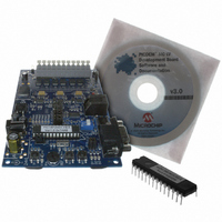
BOARD DEV PICDEM MC LV
Manufacturer
Microchip Technology
Series
PICDEM™r
Specifications of DM183021
Main Purpose
Power Management, Motor Control
Embedded
No
Utilized Ic / Part
PIC18F, dsPIC30F
Primary Attributes
Brushless DC (BLDC) Motors, 3-Phase, 1A, LIN, SPI, PWM Interface
Secondary Attributes
Graphical User Interface
Silicon Manufacturer
Microchip
Silicon Core Number
PIC18F2431, DsPIC30F3010
Core Architecture
PIC
Core Sub-architecture
PIC18F, PIC30F
Silicon Family Name
Piccolo
Lead Free Status / RoHS Status
Lead free / RoHS Compliant
Available stocks
Company
Part Number
Manufacturer
Quantity
Price
Company:

Part Number:
DM183021
Manufacturer:
Microchip Technology
Quantity:
135
Company:
Part Number:
DM183021
Manufacturer:
MICROCHIP
Quantity:
12 000


3.1
3.2
3.3
© 2006 Microchip Technology Inc.
Chapter 3. Getting Started with PIC18FXX31 MCUs
INTRODUCTION
HIGHLIGHTS
PICDEM MC LV DEVELOPMENT BOARD SETUP
This chapter provides instructions on how to set up the PICDEM MC LV Development
Board using the PIC18FXX31 devices.
This item discussed in this chapter is:
• PICDEM MC LV Development Board Setup
The following procedure describes how to set up the PICDEM MC LV Development
Board to run with a PIC18FXX31 device.
1. Place the PICDEM MC LV Development Board on a sturdy platform.
2. Make sure the PIC18F2331 or the PIC18F2431 is mounted in the “PIC” socket on U1.
3. Connect the 24V power supply to J20.
4. Determine the algorithm you want to run the motor. The following two options are
5. Program the part with the desired algorithm. For generating a project and pro-
6. Disconnect the power supply and complete jumper settings and motor connec-
The PICDEM MC LV Development Board is intended to drive 3-phase BLDC motors.
Before connecting the motor, make sure that the power rating of the motor is equal
or less than the power rating of the board, as given in Appendix B. “Electrical Spec-
ifications”. Also, make sure that the jumper settings are correct for the firmware
programmed into the target PIC
with this warning could lead to malfunction of the board and/or the motor and could
possibly be hazardous to the development staff.
Before beginning the start-up procedure, do a visual check of the board and the
motor to be connected for any mechanical damage. If damage is found, DO NOT
power-up the board. Otherwise, you may further damage the equipment.
Immediately contact Microchip’s local office or distributor for information.
Note:
• Speed control using Hall sensors
• Sensorless control
LED D7 (red) should turn on. If it does not turn on, check the polarity of the power
supply connector. If it is correct and the LED D7 still does not turn on, disconnect
power to the board and contact Microchip’s local office or distributor.
available:
gramming using MPLAB
User’s Guide” (DS51331).
tions as given in the following table. The wire colors mentioned in the brackets
are for the Hurst NT Dynamo motor, available from Microchip as an accessory,
part number AC300020.
DO NOT connect the motor wires to the board.
®
ICD 2, refer to the “MPLAB
®
MCU mounted on the socket. Failure to comply
WARNING
DEVELOPMENT BOARD
PICDEM™ MC LV
®
ICD 2 In-Circuit Debugger
DS51554B-page 15
Related parts for DM183021
Image
Part Number
Description
Manufacturer
Datasheet
Request
R

Part Number:
Description:
Manufacturer:
Microchip Technology Inc.
Datasheet:
Part Number:
Description:
Manufacturer:
Microchip Technology Inc.
Datasheet:
Part Number:
Description:
Manufacturer:
Microchip Technology Inc.
Datasheet:
Part Number:
Description:
Manufacturer:
Microchip Technology Inc.
Datasheet:
Part Number:
Description:
Manufacturer:
Microchip Technology Inc.
Datasheet:
Part Number:
Description:
Manufacturer:
Microchip Technology Inc.
Datasheet:
Part Number:
Description:
Manufacturer:
Microchip Technology Inc.
Datasheet:
Part Number:
Description:
Manufacturer:
Microchip Technology Inc.
Datasheet: