DM183021 Microchip Technology, DM183021 Datasheet - Page 23
DM183021
Manufacturer Part Number
DM183021
Description
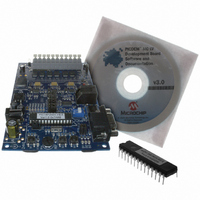
BOARD DEV PICDEM MC LV
Manufacturer
Microchip Technology
Series
PICDEM™r
Specifications of DM183021
Main Purpose
Power Management, Motor Control
Embedded
No
Utilized Ic / Part
PIC18F, dsPIC30F
Primary Attributes
Brushless DC (BLDC) Motors, 3-Phase, 1A, LIN, SPI, PWM Interface
Secondary Attributes
Graphical User Interface
Silicon Manufacturer
Microchip
Silicon Core Number
PIC18F2431, DsPIC30F3010
Core Architecture
PIC
Core Sub-architecture
PIC18F, PIC30F
Silicon Family Name
Piccolo
Lead Free Status / RoHS Status
Lead free / RoHS Compliant
Available stocks
Company
Part Number
Manufacturer
Quantity
Price
Company:

Part Number:
DM183021
Manufacturer:
Microchip Technology
Quantity:
135
Company:
Part Number:
DM183021
Manufacturer:
MICROCHIP
Quantity:
12 000


© 2006 Microchip Technology Inc.
• Speed Set Control – The user can set the target run speed for the motor with this
• Phase Current Display – Displays the current draw for the indicated motor windings
• Temperature Display – This gives the approximate temperature of the inverter
• Control Buttons – A total of four active motor controls are provided. The first two
• Communication Control – This area provides user controls for the serial com-
spin box by either direct entry or using the up/down controls. The input is specified
in RPM for all applications. Left clicking on the control, or pressing the <Enter> or
<Tab> keys after entering a speed, starts the motor running.
in amperes. Information is given in analog gauge and digital (text) format. The num-
ber of gauges that are used at any time reflect the motor type and current sensing
configuration; for example, using one current transducer will result in one active
gauge. The example shown in Figure 4-1 is typical for 3-phase current sensing.
As with the speed display, the different color zones represent average safe and
hazardous operating ranges based on the capabilities of the development board
being used. For the PICDEM MC LV Development Board, the safe operating limit
is 6A. The actual safe operating range should be determined from the motor’s
name plate and data sheet.
power module in degrees Celsius, as both an analog thermometer and a text
value. The arrow at the left of the thermometer indicates the event temperature for
overtemperature Faults set in the controller firmware. This display is not
implemented in the current version.
start and stop the motor, respectively. The motor’s current status disables the cor-
responding button; that is, the Run is disabled and the Stop button is enabled once
the motor is running. Starting the motor by left clicking on the control, or pressing the
<Enter> or <Tab> keys on the Set Speed control also disables the Run button.
The third button, Direction, toggles the direction of rotation. The Setup button at
the extreme right launches the Setup window display (described in
Section 4.5 “The Setup Window”).
Two additional buttons, Pattern and History, are not implemented in this version
of the Motor Control GUI. They will appear shaded.
munication link to the board, as well as a real-time status indicator. Clicking COM
Setup launches the COM Port Setting window; this allows the user to select the
serial port and baud rate settings for communicating with the board. By clicking on
Auto Connect, the Motor Control GUI will automatically attempt to communicate
with the board each time the GUI is launched, using the most recently entered
COM parameters. Once connected, COM Setup becomes unavailable.
The Connect/Abort button is used to establish or break a serial link with the
board. When a link is established, the Connect label changes to Abort and COM
Setup becomes unavailable. When the link is broken by clicking on Abort, COM
Setup becomes available for configuration.
The indicator at the extreme left shows the status of the serial link. When a link is
established, the indicator is solid green. When a connection is being established,
the indicator flashes green. Should the link fail, the indicator changes to solid red.
Located to the right is a scrolling message display; this shows the current con-
nection status, the device being controlled and the current version of the motor
control firmware. A real-time clock based on system clock time is provided at the
extreme right of the display.
Note:
Identification of the microcontroller and firmware happens when the Motor
Control GUI is launched and the serial link is first established. If the control-
ler and/or firmware is changed, the application may not always see this
when the serial link is re-established. Always close and restart the Motor
Control GUI when changing the microcontroller or firmware.
Using the Microchip Motor Control GUI
DS51554B-page 19
Related parts for DM183021
Image
Part Number
Description
Manufacturer
Datasheet
Request
R

Part Number:
Description:
Manufacturer:
Microchip Technology Inc.
Datasheet:
Part Number:
Description:
Manufacturer:
Microchip Technology Inc.
Datasheet:
Part Number:
Description:
Manufacturer:
Microchip Technology Inc.
Datasheet:
Part Number:
Description:
Manufacturer:
Microchip Technology Inc.
Datasheet:
Part Number:
Description:
Manufacturer:
Microchip Technology Inc.
Datasheet:
Part Number:
Description:
Manufacturer:
Microchip Technology Inc.
Datasheet:
Part Number:
Description:
Manufacturer:
Microchip Technology Inc.
Datasheet:
Part Number:
Description:
Manufacturer:
Microchip Technology Inc.
Datasheet: