DM183021 Microchip Technology, DM183021 Datasheet - Page 25
DM183021
Manufacturer Part Number
DM183021
Description
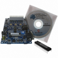
BOARD DEV PICDEM MC LV
Manufacturer
Microchip Technology
Series
PICDEM™r
Specifications of DM183021
Main Purpose
Power Management, Motor Control
Embedded
No
Utilized Ic / Part
PIC18F, dsPIC30F
Primary Attributes
Brushless DC (BLDC) Motors, 3-Phase, 1A, LIN, SPI, PWM Interface
Secondary Attributes
Graphical User Interface
Silicon Manufacturer
Microchip
Silicon Core Number
PIC18F2431, DsPIC30F3010
Core Architecture
PIC
Core Sub-architecture
PIC18F, PIC30F
Silicon Family Name
Piccolo
Lead Free Status / RoHS Status
Lead free / RoHS Compliant
Available stocks
Company
Part Number
Manufacturer
Quantity
Price
Company:

Part Number:
DM183021
Manufacturer:
Microchip Technology
Quantity:
135
Company:
Part Number:
DM183021
Manufacturer:
MICROCHIP
Quantity:
12 000


© 2006 Microchip Technology Inc.
The configuration for motion feedback sensors is selectively enabled by selecting the
appropriate check boxes in Feedback Device. When Hall effect sensors alone are
used, the Hall Sensor Phase Angle and MFM Filter Prescaler (Motion Feedback
Module) may be configured; the other options are disabled. When optical encoders are
enabled, the Encoder PPR (Pulses Per Revolution), QEI update mode and MFM
Filter Prescaler may be configured; Hall effect configuration is unavailable. (The use
of the QEI update mode and MFM Filter Prescaler options is discussed in detail in
Section 16 “Motion Feedback Module” of the “PIC18F2331/2431/4331/4431 Data
Sheet” (DS39616).
For motors with integrated motion feedback sensors, information on the sensor type
and arrangement is also found in the motor data sheet. External shaft mounted
encoders should also have the required information in their data sheets.
4.5.2
The System Parameters options will vary, depending on the motor control principle
being used by the firmware.
Proportional-Integral-Derivative (PID) systems are most often employed in closed-loop
operation, where constant speed or constant torque is required. Options 1 through 6
will only be available when a PID control algorithm is used.
Acceleration and deceleration are defined as RPS/s for most applications. For
induction motors running in open-loop applications, they are defined as Hz/s.
The Input Voltage is the actual supply voltage to the board. With the drive voltage level
established under Motor Parameters, it is used to calculate the limits on the PCPWM
duty cycle necessary to generate the drive voltage from the input voltage.
The PWM Frequency determines the resolution of the control firmware. The
drop-down combo box presents a fixed range of values depending on the firmware
application and microcontroller.
4.5.3
The System Limits reflect the maximums of both the motor and the board being used.
Voltage Limit, or the maximum voltage delivered to the motor, is limited at the input DC
voltage level.
Current Limit is set at the lesser of the maximum current rating for the motor or the
maximum capacity of the board. For the PICDEM MC LV Development Board, this is 4.0A.
Speed Limit is set at the value given in the motor’s data sheet, or at a predetermined
speed set by the particular motor data file.
Note:
Note:
Not all motors may be able to run at the maximum speed defined by the Speed
Limit parameter. It should be regarded as an upper limit and not the motor’s
expected maximum speed.
System Parameters
System Limits
The Hall effect and optical sensors are mutually exclusive; it is not possible for
some control methods to use both types at once. In these cases, checking the
appropriate box enables all configuration options. Of course, selecting the
None option in Feedback Device disables all sensor configuration options.
The V/F Curve control is not available in the current version of the Motor
Control GUI.
Using the Microchip Motor Control GUI
CAUTION
DS51554B-page 21
Related parts for DM183021
Image
Part Number
Description
Manufacturer
Datasheet
Request
R

Part Number:
Description:
Manufacturer:
Microchip Technology Inc.
Datasheet:
Part Number:
Description:
Manufacturer:
Microchip Technology Inc.
Datasheet:
Part Number:
Description:
Manufacturer:
Microchip Technology Inc.
Datasheet:
Part Number:
Description:
Manufacturer:
Microchip Technology Inc.
Datasheet:
Part Number:
Description:
Manufacturer:
Microchip Technology Inc.
Datasheet:
Part Number:
Description:
Manufacturer:
Microchip Technology Inc.
Datasheet:
Part Number:
Description:
Manufacturer:
Microchip Technology Inc.
Datasheet:
Part Number:
Description:
Manufacturer:
Microchip Technology Inc.
Datasheet: