DM183021 Microchip Technology, DM183021 Datasheet - Page 22
DM183021
Manufacturer Part Number
DM183021
Description
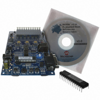
BOARD DEV PICDEM MC LV
Manufacturer
Microchip Technology
Series
PICDEM™r
Specifications of DM183021
Main Purpose
Power Management, Motor Control
Embedded
No
Utilized Ic / Part
PIC18F, dsPIC30F
Primary Attributes
Brushless DC (BLDC) Motors, 3-Phase, 1A, LIN, SPI, PWM Interface
Secondary Attributes
Graphical User Interface
Silicon Manufacturer
Microchip
Silicon Core Number
PIC18F2431, DsPIC30F3010
Core Architecture
PIC
Core Sub-architecture
PIC18F, PIC30F
Silicon Family Name
Piccolo
Lead Free Status / RoHS Status
Lead free / RoHS Compliant
Available stocks
Company
Part Number
Manufacturer
Quantity
Price
Company:

Part Number:
DM183021
Manufacturer:
Microchip Technology
Quantity:
135
Company:
Part Number:
DM183021
Manufacturer:
MICROCHIP
Quantity:
12 000


PICDEM™ MC LV Development Board
4.4
DS51554B-page 18
THE MAIN WINDOW (CONTROL PANEL)
FIGURE 4-1:
The control panel allows the user to control motor speed and rotation direction in a way
that is similar to Stand-Alone mode. It also allows users to access the Setup and
Pattern programming displays.
The control panel’s features include:
• Motor and Control Method Display – When the motor control firmware is
• Speed/Direction Display – Displays the actual speed of the motor as determined
• Fault Display – A scrolling text display indicates the state of the Fault conditions
appropriately configured (such as the demonstration applications included with
the development kit), the scrolling display indicates the type of motor and control
firmware that has been programmed to the PICDEM MC LV Development Board.
either by sensors, or Back EMF approximation, in both tachometer and digital
(text) formats. Below the tachometer is a direction indicator, showing the direction
of motor revolution relative to the default direction with an arrow and text. Speed
for all applications in Open-Loop mode is shown in RPM.
The full-scale value of the tachometer and the colored zones reflect average safe
and hazardous values for the type of motor selected, based on the rated and max-
imum safe speeds. The full-scale value is determined by the speed limit defined in
the Setup window, plus an additional margin. The upper boundary of the green
range represents the motor’s rated speed. The upper blue boundary is set to
scale the maximum safe speed well into the red area; generally, this boundary is
halfway between the rated and full-scale speeds. The values may be changed in
the Setup window to reflect the actual performance limitations of the motor.
monitored by the PICDEM MC LV Development Board. Under normal conditions,
it will display a scrolling “No Fault” message and a green indicator. Should a Fault
condition occur, the indicator will change to blinking red; the text will also change
to red and the message will indicate the specific Fault event(s).
THE CONTROL PANEL VIEW
© 2006 Microchip Technology Inc.
Related parts for DM183021
Image
Part Number
Description
Manufacturer
Datasheet
Request
R

Part Number:
Description:
Manufacturer:
Microchip Technology Inc.
Datasheet:
Part Number:
Description:
Manufacturer:
Microchip Technology Inc.
Datasheet:
Part Number:
Description:
Manufacturer:
Microchip Technology Inc.
Datasheet:
Part Number:
Description:
Manufacturer:
Microchip Technology Inc.
Datasheet:
Part Number:
Description:
Manufacturer:
Microchip Technology Inc.
Datasheet:
Part Number:
Description:
Manufacturer:
Microchip Technology Inc.
Datasheet:
Part Number:
Description:
Manufacturer:
Microchip Technology Inc.
Datasheet:
Part Number:
Description:
Manufacturer:
Microchip Technology Inc.
Datasheet: