DM183021 Microchip Technology, DM183021 Datasheet - Page 32
DM183021
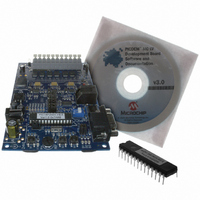
Manufacturer Part Number
DM183021
Description
BOARD DEV PICDEM MC LV
Manufacturer
Microchip Technology
Series
PICDEM™r
Specifications of DM183021
Main Purpose
Power Management, Motor Control
Embedded
No
Utilized Ic / Part
PIC18F, dsPIC30F
Primary Attributes
Brushless DC (BLDC) Motors, 3-Phase, 1A, LIN, SPI, PWM Interface
Secondary Attributes
Graphical User Interface
Silicon Manufacturer
Microchip
Silicon Core Number
PIC18F2431, DsPIC30F3010
Core Architecture
PIC
Core Sub-architecture
PIC18F, PIC30F
Silicon Family Name
Piccolo
Lead Free Status / RoHS Status
Lead free / RoHS Compliant
Available stocks
Company
Part Number
Manufacturer
Quantity
Price
Company:

Part Number:
DM183021
Manufacturer:
Microchip Technology
Quantity:
135
Company:
Part Number:
DM183021
Manufacturer:
MICROCHIP
Quantity:
12 000


PICDEM™ MC LV Development Board
DS51554B-page 28
There are 6 sectors, each 60 degrees wide, which accumulate to give one 360 degree
electrical revolution of the motor. In each sector, two windings are excited: one with a
high voltage and the other with a low voltage. The third winding is not excited. As the
rotor rotates from one sector to another, a new set of windings is excited. The sequence
of excitation in each sector is provided by the motor manufacturer. The winding in each
sector that is not excited will be influenced by the Back EMF voltage. This voltage is
not high or low, but a falling or rising voltage level, going symmetrically from a
high-to-low or a low-to-high. It crosses the center, or star point voltage, at about
30 degrees before the next commutation point of the rotor. This center, or star point
voltage, is also referred to as the zero-crossing voltage. Its value is exactly half the volt-
age applied to the excited windings of the motor. The dsPIC device uses its fast ADC
to sense the zero-cross point. Having sensed the zero-cross point, it can predict the
time required for the next commutation phase. The zero-cross sensing and drive of the
motor is shown in Figure 7-2.
FIGURE 7-2:
The PWM signals drive three MOSFET drivers (IR2101s), which in turn, drive the
3-phase bridge inverter connected to the 3 motor windings (see Appendix A. “Circuit
Schematics of the Board”). The motor windings are driven with 24V. This voltage is
scaled down to about 1.8V full scale when sensed by the ADC inputs of the dsPIC
device. The scaling for each winding is done by resistor pairs, R34/R36, R41/R44 and
R49/R52 (see Appendix A. “Circuit Schematics of the Board”). The bus voltage is
sensed and scaled down by resistor pair, R63/R64.
Note:
dsPIC30F2010
All the resistor pairs should have the same value for a given motor voltage.
The resistor pairs used on the PICDEM MC LV Development Board give a
full-scale value of about 2.4V and so, the zero-cross voltage is about 1.2V.
This is based on a motor voltage of 24V.
PWM3H
PWM2H
PWM1H
PWM3L
PWM2L
PWM1L
HARDWARE BLOCK DIAGRAM
FLTA
AN0
AN1
AN2
AN3
AN4
AN5
Demand
Fault
V
Phase Terminal Voltage Feedback
DC
3-Phase
Inverter
I
BUS
R49
R41
© 2006 Microchip Technology Inc.
R34
R52
R36
R44
V
DC
BLDC
V
BUS
R63
R64
Related parts for DM183021
Image
Part Number
Description
Manufacturer
Datasheet
Request
R

Part Number:
Description:
Manufacturer:
Microchip Technology Inc.
Datasheet:
Part Number:
Description:
Manufacturer:
Microchip Technology Inc.
Datasheet:
Part Number:
Description:
Manufacturer:
Microchip Technology Inc.
Datasheet:
Part Number:
Description:
Manufacturer:
Microchip Technology Inc.
Datasheet:
Part Number:
Description:
Manufacturer:
Microchip Technology Inc.
Datasheet:
Part Number:
Description:
Manufacturer:
Microchip Technology Inc.
Datasheet:
Part Number:
Description:
Manufacturer:
Microchip Technology Inc.
Datasheet:
Part Number:
Description:
Manufacturer:
Microchip Technology Inc.
Datasheet: