OM6272,598 NXP Semiconductors, OM6272,598 Datasheet - Page 3
OM6272,598
Manufacturer Part Number
OM6272,598
Description
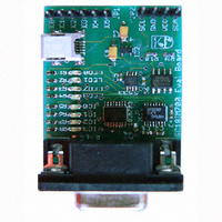
DEMO BOARD UART TO I2C
Manufacturer
NXP Semiconductors
Datasheet
1.OM6272598.pdf
(10 pages)
Specifications of OM6272,598
Main Purpose
Interface, I2C Master to UART
Embedded
No
Utilized Ic / Part
SC18IM700
Primary Attributes
UART to I2C Master/GPIO Bridge, 4-Bit LED Dimmer
Secondary Attributes
Graphic User Interface
Lead Free Status / RoHS Status
Not applicable / Not applicable
Other names
568-3512
935282853598
OM6272
935282853598
OM6272


Philips Semiconductors
1. Introduction
2. PCA9531: LED blinker
AN10397_1
Application note
Philips Semiconductors recently introduced a whole new family of devices called
‘the Bridges’. These devices are intended to transform data from one serial bus to another
serial bus, and this transformation allows the host to control devices that have serial host
bus interfaces that are not native to the system.
One such scenario is the I
I
temperature sensors, analog-to-digital or digital-to-analog converters, LED blinkers and
I/O expanders. To use these devices in the system, a host must have an integrated
I
Philips Semiconductors’ SC18IM700—an I
is the perfect choice in the case where the host does not have an integrated I
controller on-board, and the system designer wishes to use I
system. The SC18IM700 does not require any programming at all other than the code to
write and read from the host’s UART port. This non-programming is possible because
SC18IM700 communicates with the host through a series of messages that are based on
ASCII characters.
This application note shows how a host can control, setup, read and write to any I
devices through this UART-to-I
are built around an LED blinker from Philips Semiconductors, the PCA9531. Besides the
I
programmable I/O port. These eight general purpose I/O pins can be configured to the
following modes: input only, open-drain output, push-pull output or quasi-bidirectional
input/output.
The PCA9531 is an 8-bit I
256 discrete steps for Red/Green/Blue (RGB) color mixing and backlight applications.
The initial setup sequence programs the two blink rates and duty cycles for each individual
PWM. From then on, only one command from the bus master is required to turn individual
LEDs ON, OFF, BLINK RATE 1 or BLINK RATE 2. Based on the programmed frequency
and duty cycle, BLINK RATE 1 and BLINK RATE 2 will cause the LEDs to appear at a
different brightness or blink at periods up to 1.69 second. The open-drain outputs directly
drive the LEDs with maximum output sink current of 25 mA per bit and 100 mA per
package.
Please refer to the PCA9531 data sheet for more detail about this device and its internal
registers’ usage. The following steps to program the part are extracted from the example
in the data sheet, page 11.
2
2
2
C-bus interface to communicate with a host. Some of such devices are: EEPROMs,
C-bus controller on-board, or it must have an external, stand-alone I
C-bus control function, the SC18IM700 also contains a general-purpose 8-bit
Rev. 01 — 5 December 2005
2
2
C-bus and SMBus I/O expander optimized for dimming LEDs in
C-bus interface. There are wide ranges of devices that have an
How to use the SC18IM700 to control any I
2
C controller. The examples used in this application note
2
C-bus controller with a UART host interface—
© Koninklijke Philips Electronics N.V. 2005. All rights reserved.
2
C-bus related devices in the
2
C-bus controller.
AN10397
2
C-bus device
2
C-bus
2
C-bus
3 of 10
Related parts for OM6272,598
Image
Part Number
Description
Manufacturer
Datasheet
Request
R

Part Number:
Description:
Display Modules & Development Tools UART TO I2C MASTER BRIDGE DEMO BOARD
Manufacturer:
NXP Semiconductors

Part Number:
Description:
NXP Semiconductors designed the LPC2420/2460 microcontroller around a 16-bit/32-bitARM7TDMI-S CPU core with real-time debug interfaces that include both JTAG andembedded trace
Manufacturer:
NXP Semiconductors
Datasheet:

Part Number:
Description:
NXP Semiconductors designed the LPC2458 microcontroller around a 16-bit/32-bitARM7TDMI-S CPU core with real-time debug interfaces that include both JTAG andembedded trace
Manufacturer:
NXP Semiconductors
Datasheet:
Part Number:
Description:
NXP Semiconductors designed the LPC2468 microcontroller around a 16-bit/32-bitARM7TDMI-S CPU core with real-time debug interfaces that include both JTAG andembedded trace
Manufacturer:
NXP Semiconductors
Datasheet:
Part Number:
Description:
NXP Semiconductors designed the LPC2470 microcontroller, powered by theARM7TDMI-S core, to be a highly integrated microcontroller for a wide range ofapplications that require advanced communications and high quality graphic displays
Manufacturer:
NXP Semiconductors
Datasheet:
Part Number:
Description:
NXP Semiconductors designed the LPC2478 microcontroller, powered by theARM7TDMI-S core, to be a highly integrated microcontroller for a wide range ofapplications that require advanced communications and high quality graphic displays
Manufacturer:
NXP Semiconductors
Datasheet:
Part Number:
Description:
The Philips Semiconductors XA (eXtended Architecture) family of 16-bit single-chip microcontrollers is powerful enough to easily handle the requirements of high performance embedded applications, yet inexpensive enough to compete in the market for hi
Manufacturer:
NXP Semiconductors
Datasheet:
Part Number:
Description:
The XA-S3 device is a member of Philips Semiconductors? XA(eXtended Architecture) family of high performance 16-bitsingle-chip microcontrollers
Manufacturer:
NXP Semiconductors
Datasheet:

Part Number:
Description:
The NXP BlueStreak LH75401/LH75411 family consists of two low-cost 16/32-bit System-on-Chip (SoC) devices
Manufacturer:
NXP Semiconductors
Datasheet:
Part Number:
Description:
The NXP LPC3130/3131 combine an 180 MHz ARM926EJ-S CPU core, high-speed USB2
Manufacturer:
NXP Semiconductors
Datasheet:
Part Number:
Description:
The NXP LPC3141 combine a 270 MHz ARM926EJ-S CPU core, High-speed USB 2
Manufacturer:
NXP Semiconductors
Part Number:
Description:
The NXP LPC3143 combine a 270 MHz ARM926EJ-S CPU core, High-speed USB 2
Manufacturer:
NXP Semiconductors

Part Number:
Description:
The NXP LPC3152 combines an 180 MHz ARM926EJ-S CPU core, High-speed USB 2
Manufacturer:
NXP Semiconductors
Part Number:
Description:
The NXP LPC3154 combines an 180 MHz ARM926EJ-S CPU core, High-speed USB 2
Manufacturer:
NXP Semiconductors