OM6272,598 NXP Semiconductors, OM6272,598 Datasheet - Page 6
OM6272,598
Manufacturer Part Number
OM6272,598
Description
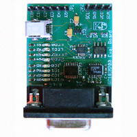
DEMO BOARD UART TO I2C
Manufacturer
NXP Semiconductors
Datasheet
1.OM6272598.pdf
(10 pages)
Specifications of OM6272,598
Main Purpose
Interface, I2C Master to UART
Embedded
No
Utilized Ic / Part
SC18IM700
Primary Attributes
UART to I2C Master/GPIO Bridge, 4-Bit LED Dimmer
Secondary Attributes
Graphic User Interface
Lead Free Status / RoHS Status
Not applicable / Not applicable
Other names
568-3512
935282853598
OM6272
935282853598
OM6272


Philips Semiconductors
AN10397_1
Application note
Fig 3. ‘Read after Write’ command format
S CHAR.
SLAVE ADR.
+ W
The command begins with an ‘S’ character as the first byte, the second byte specifies the
I
set to a logic 0. The third byte indicates the number of data bytes in the message (DATA 1
to DATA N), and the last byte ended with the ‘P’ character.
To turn on and blink the LED, the host would send a message to the SC18IM700 as
follows: S C0 07 11 97 80 00 40 55 FA P.
Once the SC18IM700 receives this message from host it will translate and will send the
same message through the I
If the host wishes to read the PCA9531 internal registers to make sure they are correctly
set after the host has written to them, the ‘Read after Write’ command can be used for that
purpose. The format for the ‘Read after Write’ command is as shown in
Using the first example the host sends the following message to the SC18IM700:
SC18IM will send the message to PCA9531, then will read seven bytes from PCA9531
and sends them to the host automatically. The host will receive the following byte from
SC18IM700 through its UART port:
The host can also ask SC18IM700 to automatically send an I
information to the host after SC18IM700 has sent the host’s message to an I
The host can do this by sending a ‘Register Read’ command to read the I2Cstatus register
after any normal I
following message to SC18IM700:
Once the message is sent to the I
the I2C_OK (hex code 0xF0) status to the host. See Table 9 of the data sheet for other
I2C Status Code.
Upon receiving the I2C_OK status the host can send another message to SC18IM700.
2
C-bus slave address of the I
11 97 80 00 40 55 FA
S C0 07 11 97 80 00 40 55 FA S C1 07 P
S C0 07 11 97 80 00 40 55 FA P R 0A P
OF BYTES
NUMBER
2
C-bus message. Using the above example, the host would send the
DATA 1
Rev. 01 — 5 December 2005
2
How to use the SC18IM700 to control any I
2
C-bus to the PCA9531. The LED should be now blinking.
C-bus device, where ‘W’ is the least significant bit and it is
2
DATA N
C-bus device at address 0xC0, SC18IM700 will send
S CHAR.
SLAVE ADR. + R
© Koninklijke Philips Electronics N.V. 2005. All rights reserved.
2
C-bus’ transaction status
OF BYTES
NUMBER
AN10397
Figure
2
P CHAR.
C-bus device
2
C-bus slave.
3.
6 of 10
Related parts for OM6272,598
Image
Part Number
Description
Manufacturer
Datasheet
Request
R

Part Number:
Description:
Display Modules & Development Tools UART TO I2C MASTER BRIDGE DEMO BOARD
Manufacturer:
NXP Semiconductors

Part Number:
Description:
NXP Semiconductors designed the LPC2420/2460 microcontroller around a 16-bit/32-bitARM7TDMI-S CPU core with real-time debug interfaces that include both JTAG andembedded trace
Manufacturer:
NXP Semiconductors
Datasheet:

Part Number:
Description:
NXP Semiconductors designed the LPC2458 microcontroller around a 16-bit/32-bitARM7TDMI-S CPU core with real-time debug interfaces that include both JTAG andembedded trace
Manufacturer:
NXP Semiconductors
Datasheet:
Part Number:
Description:
NXP Semiconductors designed the LPC2468 microcontroller around a 16-bit/32-bitARM7TDMI-S CPU core with real-time debug interfaces that include both JTAG andembedded trace
Manufacturer:
NXP Semiconductors
Datasheet:
Part Number:
Description:
NXP Semiconductors designed the LPC2470 microcontroller, powered by theARM7TDMI-S core, to be a highly integrated microcontroller for a wide range ofapplications that require advanced communications and high quality graphic displays
Manufacturer:
NXP Semiconductors
Datasheet:
Part Number:
Description:
NXP Semiconductors designed the LPC2478 microcontroller, powered by theARM7TDMI-S core, to be a highly integrated microcontroller for a wide range ofapplications that require advanced communications and high quality graphic displays
Manufacturer:
NXP Semiconductors
Datasheet:
Part Number:
Description:
The Philips Semiconductors XA (eXtended Architecture) family of 16-bit single-chip microcontrollers is powerful enough to easily handle the requirements of high performance embedded applications, yet inexpensive enough to compete in the market for hi
Manufacturer:
NXP Semiconductors
Datasheet:
Part Number:
Description:
The XA-S3 device is a member of Philips Semiconductors? XA(eXtended Architecture) family of high performance 16-bitsingle-chip microcontrollers
Manufacturer:
NXP Semiconductors
Datasheet:

Part Number:
Description:
The NXP BlueStreak LH75401/LH75411 family consists of two low-cost 16/32-bit System-on-Chip (SoC) devices
Manufacturer:
NXP Semiconductors
Datasheet:
Part Number:
Description:
The NXP LPC3130/3131 combine an 180 MHz ARM926EJ-S CPU core, high-speed USB2
Manufacturer:
NXP Semiconductors
Datasheet:
Part Number:
Description:
The NXP LPC3141 combine a 270 MHz ARM926EJ-S CPU core, High-speed USB 2
Manufacturer:
NXP Semiconductors
Part Number:
Description:
The NXP LPC3143 combine a 270 MHz ARM926EJ-S CPU core, High-speed USB 2
Manufacturer:
NXP Semiconductors

Part Number:
Description:
The NXP LPC3152 combines an 180 MHz ARM926EJ-S CPU core, High-speed USB 2
Manufacturer:
NXP Semiconductors
Part Number:
Description:
The NXP LPC3154 combines an 180 MHz ARM926EJ-S CPU core, High-speed USB 2
Manufacturer:
NXP Semiconductors