HFBR-0410 Avago Technologies US Inc., HFBR-0410 Datasheet - Page 10
HFBR-0410
Manufacturer Part Number
HFBR-0410
Description
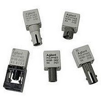
KIT EVAL FIBER OPTIC 5MBD
Manufacturer
Avago Technologies US Inc.
Specifications of HFBR-0410
Main Purpose
Interface, Fiber Optics
Embedded
No
Utilized Ic / Part
HFBR-1412, HFBR-2412
Primary Attributes
DC ~ 5MBd TTL
Secondary Attributes
ST Connectors
Silicon Core Number
HFBR-1412, HFBR-2412
Kit Contents
TX/RX Mods, Cable, Pol Kit, SW, Pwr. Sup
Silicon Family Name
HFBR-0400
Features
Dc To 5 MBd TTL Compatible Fiber Optic Component
Lead Free Status / RoHS Status
Contains lead / RoHS non-compliant
Other names
516-2138
HFBR-0410
HFBR-0410


Typical Link Data
HFBR-0400Z Series
Description
The following technical data is taken from 4 popular links
using the HFBR-0400Z series: the 5 MBd link, Ethernet 20
MBd link, Token Ring 32 MBd link, and the corresponds
to transceiver solutions combining the HFBR-0400Z se-
ries components and various recommended transceiver
design circuits using off-the-shelf electrical components.
This data is meant to be regarded as an example of typi-
cal link performance for a given design and does not call
out any link limitations. Please refer to the appropriate
application note given for each link to obtain more in-
formation.
5 MBd Link (HFBR-14xxZ/24x2Z)
Link Performance -40 °C to +85 °C unless otherwise specified
Notes:
1. OPB at T
2. Synchronous data rate limit is based on these assumptions: a) 50% duty factor modulation, e.g., Manchester I or BiPhase Manchester II; b)
3. Asynchronous data rate limit is based on these assumptions: a) NRZ data; b) arbitrary timing-no duty factor restriction; c) TTL threshold.
10
Parameter
Optical Power Budget
with 50/125 μm fiber
Optical Power Budget
with 62.5/125 μm fiber
Optical Power Budget
with 100/140 μm fiber
Optical Power Budget
with 200 μm fiber
Date Rate Synchronous
Asynchronous
Propagation Delay
LOW to HIGH
Propagation Delay
HIGH to LOW
System Pulse Width
Distortion
Bit Error Rate
continuous data; c) PLL Phase Lock Loop demodulation; d) TTL threshold.
A
= -40 to +85 °C, V
CC
= 5.0 V dc, IF ON = 60 mA. P
Symbol
OPB
OPB
OPB
OPB
t
t
t
BER
PLH
PHL
PLH
50
62.5
100
200
- t
PHL
Min.
4.2
8.0
8.0
12
dc
dc
R
= -24 dBm peak.
Typ.
9.6
15
15
20
72
46
26
Max.
5
2.5
10
-9
Units
dB
dB
dB
dB
MBd
MBd
ns
ns
ns
Conditions
HFBR-14x4Z/24x2Z
NA = 0.2
HFBR-14x4Z/24x2Z
NA = 0.27
HFBR-14x2Z/24x2Z
NA = 0.30
HFBR-14x2Z/24x2Z
NA = 0.37
T
P
Fiber cable length =
1 m
Data rate <5 Bd
P
A
R
R
= +25 °C
= -21 dBm peak
> -24 dBm peak
Reference
Note 1
Note 1
Note 1
Note 1
Note 2
Note 3,
Fig 7
Figs 6, 7, 8
Related parts for HFBR-0410
Image
Part Number
Description
Manufacturer
Datasheet
Request
R

Part Number:
Description:
Fiber Optic Transmitters, Receivers, Transceivers 1300nm 155MBd 16-pin DIP ST Rx
Manufacturer:
Avago Technologies US Inc.

Part Number:
Description:
FIBER OPTIC TX 125 MBD 650N
Manufacturer:
Avago Technologies US Inc.
Datasheet:

Part Number:
Description:
Fiber Optic Evaluation Kit
Manufacturer:
Avago Technologies US Inc.
Datasheet:

Part Number:
Description:
RECEIVER FIBER OPTIC ST 266MBD
Manufacturer:
Avago Technologies US Inc.
Datasheet:

Part Number:
Description:
RCVR OPT HI SPEED VERS LINK HORZ
Manufacturer:
Avago Technologies US Inc.
Datasheet:

Part Number:
Description:
RCVR OPT HI SPEED VERS LINK VERT
Manufacturer:
Avago Technologies US Inc.
Datasheet:

Part Number:
Description:
TXRX OPTICAL 850NM VCSEL MT-RJ
Manufacturer:
Avago Technologies US Inc.
Datasheet:

Part Number:
Description:
TXRX MM SFP LC CONN BAIL DELATCH
Manufacturer:
Avago Technologies US Inc.
Datasheet:

Part Number:
Description:
TXRX MMF SFP GBE/FC BAIL DELATCH
Manufacturer:
Avago Technologies US Inc.
Datasheet:

Part Number:
Description:
XMITTER FIBER OPTIC 266MBD ST
Manufacturer:
Avago Technologies US Inc.
Datasheet:

Part Number:
Description:
OPTOCOUPLER GATE DRV 2A 16-SOIC
Manufacturer:
Avago Technologies US Inc.
Datasheet:
Part Number:
Description:
OPTOCOUPLER 2CH 2.5A 16-SOIC
Manufacturer:
Avago Technologies US Inc.
Datasheet:

Part Number:
Description:
OPTOCOUPLER GATE DRV 0.4A 16SOIC
Manufacturer:
Avago Technologies US Inc.
Datasheet:

Part Number:
Description:
OPTOCOUPLER 2.0A 250KHZ 8-DIP
Manufacturer:
Avago Technologies US Inc.
Datasheet:

Part Number:
Description:
OPTOCOUPLER 2.0A 250KHZ GW 8-SMD
Manufacturer:
Avago Technologies US Inc.
Datasheet: