HFBR-0410 Avago Technologies US Inc., HFBR-0410 Datasheet - Page 21
HFBR-0410
Manufacturer Part Number
HFBR-0410
Description
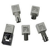
KIT EVAL FIBER OPTIC 5MBD
Manufacturer
Avago Technologies US Inc.
Specifications of HFBR-0410
Main Purpose
Interface, Fiber Optics
Embedded
No
Utilized Ic / Part
HFBR-1412, HFBR-2412
Primary Attributes
DC ~ 5MBd TTL
Secondary Attributes
ST Connectors
Silicon Core Number
HFBR-1412, HFBR-2412
Kit Contents
TX/RX Mods, Cable, Pol Kit, SW, Pwr. Sup
Silicon Family Name
HFBR-0400
Features
Dc To 5 MBd TTL Compatible Fiber Optic Component
Lead Free Status / RoHS Status
Contains lead / RoHS non-compliant
Other names
516-2138
HFBR-0410
HFBR-0410


Electrical/Optical Characteristics -40 °C to + 85 °C unless otherwise specified
Fiber sizes with core diameter d 100 μm and NA d 0.35, 4.75 V d V
Dynamic Characteristics
-40 °C to +85 °C unless otherwise specified; 4.75 V d V
Notes:
1. 2.0 mm from where leads enter case.
2. 8 mA load (5 x 1.6 mA), RL = 560 :.
3. Typical data at T
4. D is the effective diameter of the detector image on the plane of the fiber face. The numerical value is the product of the actual detector di-
5. Measured at the end of 100/140 Pm fiber optic cable with large area detector.
6. Propagation delay through the system is the result of several sequentially-occurring phenomena. Consequently it is a combination of data-
7. As the cable length is increased, the propagation delays increase at 5 ns per meter of length. Data rate, as limited by pulse width distortion, is
21
Parameter
High Level Output Current
Low Level Output Voltage
High Level Supply Current
Low Level Supply Current
Equivalent NA
Optical Port Diameter
Parameter
Peak Optical Input Power Logic Level
HIGH
Peak Optical Input Power Logic Level
LOW
Propagation Delay LOW to HIGH
Propagation Delay HIGH to LOW
CAUTION: The small junction sizes inherent to the design of these components increase the components’ susceptibility to damage
from electrostatic discharge (ESD). It is advised that normal static precautions be taken in handling and assembly of these compo-
nents to prevent damage and/or degradation which may be induced by ESD.
ameter and the lens magnification.
rate-limiting effects and of transmission-time effects. Because of this, the data-rate limit of the system must be described in terms of time
differentials between delays imposed on falling and rising edges.
not affected by increasing cable length if the optical power level at the receiver is maintained.
A
= +25 °C, V
CC
= 5.0 Vdc.
Symbol
I
V
I
I
NA
D
Symbol
P
P
t
t
OH
CCH
CCL
PLHR
PHLR
OL
RH
RL
Min
Min
-25.4
2.9
-24.0
4.0
CC
d 5.25 V; BER d 10
Typ
5
0.4
3.5
6.2
0.50
400
Typ
65
49
CC
3
3
d 5.25 V
-9
Max
250
0.5
6.3
10
Max
-40
0.1
-9.2
120
-10.0
100
Units
μA
V
mA
mA
μm
Units
dBm pk
μW pk
dBm pk
μW pk
dBm pk
μW pk
ns
ns
Conditions
V
P
I
P
V
P
V
P
Conditions
O
T
I
I
T
P
Data Rate =5
MBd
O
OL
OL
A
A
R
R
R
R
P
R
O
CC
CC
= 8 m
< -40 dBm
> -24 dBm
< -40 dBm
> -24 dBm
= +25 °C,
= +25 °C,
= -21 dBm,
= 820 nm
= 18
= 8mA
= 8mA
= 5.25 V
= 5.25 V
Reference
Note 4
Reference
Note 5
Note 5
Note 6
Related parts for HFBR-0410
Image
Part Number
Description
Manufacturer
Datasheet
Request
R

Part Number:
Description:
Fiber Optic Transmitters, Receivers, Transceivers 1300nm 155MBd 16-pin DIP ST Rx
Manufacturer:
Avago Technologies US Inc.

Part Number:
Description:
FIBER OPTIC TX 125 MBD 650N
Manufacturer:
Avago Technologies US Inc.
Datasheet:

Part Number:
Description:
Fiber Optic Evaluation Kit
Manufacturer:
Avago Technologies US Inc.
Datasheet:

Part Number:
Description:
RECEIVER FIBER OPTIC ST 266MBD
Manufacturer:
Avago Technologies US Inc.
Datasheet:

Part Number:
Description:
RCVR OPT HI SPEED VERS LINK HORZ
Manufacturer:
Avago Technologies US Inc.
Datasheet:

Part Number:
Description:
RCVR OPT HI SPEED VERS LINK VERT
Manufacturer:
Avago Technologies US Inc.
Datasheet:

Part Number:
Description:
TXRX OPTICAL 850NM VCSEL MT-RJ
Manufacturer:
Avago Technologies US Inc.
Datasheet:

Part Number:
Description:
TXRX MM SFP LC CONN BAIL DELATCH
Manufacturer:
Avago Technologies US Inc.
Datasheet:

Part Number:
Description:
TXRX MMF SFP GBE/FC BAIL DELATCH
Manufacturer:
Avago Technologies US Inc.
Datasheet:

Part Number:
Description:
XMITTER FIBER OPTIC 266MBD ST
Manufacturer:
Avago Technologies US Inc.
Datasheet:

Part Number:
Description:
OPTOCOUPLER GATE DRV 2A 16-SOIC
Manufacturer:
Avago Technologies US Inc.
Datasheet:
Part Number:
Description:
OPTOCOUPLER 2CH 2.5A 16-SOIC
Manufacturer:
Avago Technologies US Inc.
Datasheet:

Part Number:
Description:
OPTOCOUPLER GATE DRV 0.4A 16SOIC
Manufacturer:
Avago Technologies US Inc.
Datasheet:

Part Number:
Description:
OPTOCOUPLER 2.0A 250KHZ 8-DIP
Manufacturer:
Avago Technologies US Inc.
Datasheet:

Part Number:
Description:
OPTOCOUPLER 2.0A 250KHZ GW 8-SMD
Manufacturer:
Avago Technologies US Inc.
Datasheet: