101-1218 Rabbit Semiconductor, 101-1218 Datasheet - Page 39
101-1218
Manufacturer Part Number
101-1218
Description
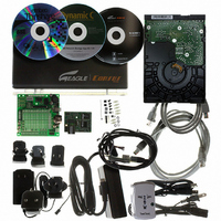
KIT APPLCTN RABBITCORE RCM4010
Manufacturer
Rabbit Semiconductor
Series
RabbitCore®r
Datasheet
1.20-101-1094.pdf
(130 pages)
Specifications of 101-1218
Main Purpose
*
Embedded
*
Utilized Ic / Part
RCM4010
Primary Attributes
*
Secondary Attributes
*
Processor To Be Evaluated
Rabbit 4000
Interface Type
Ethernet
Operating Supply Voltage
12 V
Lead Free Status / RoHS Status
Not applicable / Not applicable
Other names
316-1156


4.1.1 Memory I/O Interface
The Rabbit 4000 address lines (A0–A19) and all the data lines (D0–D7) are routed inter-
nally to the onboard flash memory and SRAM chips. I/0 write (/IOWR) and I/0 read
(/IORD) are available for interfacing to external devices. Parallel Port D is used for the
upper byte of the 16-bit memories.
Parallel Port A can also be used as an external I/O data bus to isolate external I/O from the
main data bus. Parallel Port B pins PB2–PB7 can also be used as an auxiliary address bus.
When using the auxiliary I/O bus for any reason, you must add the following line at the
beginning of your program.
Selected pins on Parallel Port E as specified in Table 2 may be used for input capture,
quadrature decoder, DMA, and pulse-width modulator purposes.
4.1.2 Other Inputs and Outputs
The status and the two SMODE pins, SMODE0 and SMODE1, can be brought out to
header J3 instead of PE5–PE7 as explained in Appendix A.6.
/RESET_IN is normally associated with the programming port, but may be used as an
external input to reset the Rabbit 4000 microprocessor and the RCM4000 memory.
/RESET_OUT is an output from the reset circuitry that can be used to reset other
peripheral devices.
User’s Manual
49
50
Pin
* PE5, PE6, and PE7 are used for the Ethernet clock and I/O signals, which ordinarily would not
#define PORTA_AUX_IO
be routed to a general-purpose I/O header to minimize noise. Therefore, the RCM4000
RabbitCore modules present the SMODE and STATUS lines to header J3.
VREF
GND
Pin Name
Table 2. RCM4000 Pinout Configurations (continued)
Analog reference
voltage
Ground
Default Use
// required to enable auxiliary I/O bus
Alternate Use
1.15 V/2.048 V/2.500 V
on-chip ref. voltage
(RCM4000 only)
Ground
Notes
33
Related parts for 101-1218
Image
Part Number
Description
Manufacturer
Datasheet
Request
R

Part Number:
Description:
COMPUTER SNGLBD BL2120 FRCTNLOCK
Manufacturer:
Rabbit Semiconductor
Datasheet:

Part Number:
Description:
KIT MESH NETWORK ADD-ON RCM4510W
Manufacturer:
Rabbit Semiconductor
Datasheet:

Part Number:
Description:
KIT DEV FOR BL2500 COYOTE
Manufacturer:
Rabbit Semiconductor
Datasheet:

Part Number:
Description:
KIT APPLICATION SIMPLE SENSOR
Manufacturer:
Rabbit Semiconductor
Datasheet:

Part Number:
Description:
KIT ETHERNET INT'L RCM3720
Manufacturer:
Rabbit Semiconductor
Datasheet:
Part Number:
Description:
KIT SERIAL-ETHERNET APPLICATION
Manufacturer:
Rabbit Semiconductor

Part Number:
Description:
KIT APPLICATION MULTI-PORT S2E
Manufacturer:
Rabbit Semiconductor
Part Number:
Description:
KIT WEB SECURE EMBEDDED RCM3700
Manufacturer:
Rabbit Semiconductor
Datasheet:
Part Number:
Description:
MODULE RABBITCORE RCM3720
Manufacturer:
Rabbit Semiconductor
Datasheet:
Part Number:
Description:
MODULE RABBITCORE RCM3220
Manufacturer:
Rabbit Semiconductor
Datasheet:
Part Number:
Description:
MODULE RABBITCORE RCM3210
Manufacturer:
Rabbit Semiconductor
Datasheet:
Part Number:
Description:
COMPUTER SGL-BOARD OP6600 W/SRAM
Manufacturer:
Rabbit Semiconductor
Datasheet:
Part Number:
Description:
COMPUTER SGL-BD BL2000 SRAM/FLSH
Manufacturer:
Rabbit Semiconductor