OM6279,598 NXP Semiconductors, OM6279,598 Datasheet - Page 15
OM6279,598
Manufacturer Part Number
OM6279,598
Description
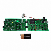
DEMO BOARD LED DIMMER
Manufacturer
NXP Semiconductors
Datasheet
1.OM6279598.pdf
(45 pages)
Specifications of OM6279,598
Main Purpose
Lighting, RGB LED Controller
Embedded
Yes, MCU, 8-Bit
Utilized Ic / Part
PCA9564PW, PCA9555PW, PCA9531PW, PCA9533DP/01
Primary Attributes
I2C Bus Controller, 1 8-Bit GPIO, 1 8-Bit LED Dimmer
Secondary Attributes
Different Demonstration Programs Through MCU
Lead Free Status / RoHS Status
Not applicable / Not applicable
Other names
568-4003
935283363598
935283363598


Philips Semiconductors
9397 750 14062
Application note
4.5 Emulation mode: battery discharge application
4.6 Auto Demo routine
4.7 RESET
Emulation mode can be described as a mode that would require external ‘stimulus’ to
show an application in a real environment. The example in the firmware shows a simple
application where a battery discharge (for example in a cell phone application) is emulated
by pushing a key. A LED controlled by a PCA9531 is used to provide visual status of the
battery level:
Table 11:
Remark: Keys in this routine have been programmed to detect a continuous push applied
to them. When pushed continuously, (+) or (-) action is performed continuously.
The Auto Demo routine shows some light effects real time RGB mixing without having to
push any buttons.
Remark: Once the Auto Demo Mode starts (after pushing key 4), the user must use the
RESET button to exit the mode.
The RESET button located in the Keypad Control Card allows the user to reinitialize the
P89LV51RD2 and the I
again at the beginning point and initiates the dialing routine.
Step
1
2
3
4
5
•
•
•
•
•
•
•
•
Emulation mode is entered by pushing key F2. LD11 starts blinking.
Pushing key 1 starts battery discharge emulation.
– LD5 to LD8 are on, indicating a fully charged battery (100 %).
– LD9 blinks slowly (1 Hz) and high duty cycle, with a Green color.
Pushing continuously Key 3 emulates a battery discharge (from 100 % with LD5 to
LD8 on, down to 0 % with LD5 to LD8 off). The different steps are explained in
Table
LED duty cycle (shorter duty cycle) to catch the user’s attention when using their cell
phone.
A reset of the emulation is performed by pushing key 6. Battery is then fully charged.
Pushing key END exits the battery discharge emulation mode. LD5 to LD9 are off.
Pushing again key END exits the Emulation mode. LD11 stops blinking.
Emulation mode is entered by pushing key F2. LD11 starts blinking
Pushing key 4 starts the auto demo mode
Battery charge
100 %
75 %
50 %
25 %
0 %
11. Principle is to change the LED color (Green, Orange, Red) and the
Battery discharge steps
Rev. 01 — 7 January 2005
2
C devices and go to a known state. It causes the firmware to start
LD5
ON
OFF
OFF
OFF
OFF
LD6
ON
ON
OFF
OFF
OFF
LD7
ON
ON
ON
OFF
OFF
LD8
ON
ON
ON
ON
OFF
© Koninklijke Philips Electronics N.V. 2005. All rights reserved.
LD9
Green - 1 Hz - 93 % duty cycle
Green - 1 Hz - 93 % duty cycle
Orange - 1 Hz - 50 % duty cycle
Red - 1 Hz - 6 % duty cycle
Red - 1 Hz - 0.4 % duty cycle
LED dimmer demoboard
AN10315
15 of 45
Related parts for OM6279,598
Image
Part Number
Description
Manufacturer
Datasheet
Request
R

Part Number:
Description:
Display Modules & Development Tools LED EVAL Board
Manufacturer:
NXP Semiconductors

Part Number:
Description:
NXP Semiconductors designed the LPC2420/2460 microcontroller around a 16-bit/32-bitARM7TDMI-S CPU core with real-time debug interfaces that include both JTAG andembedded trace
Manufacturer:
NXP Semiconductors
Datasheet:

Part Number:
Description:
NXP Semiconductors designed the LPC2458 microcontroller around a 16-bit/32-bitARM7TDMI-S CPU core with real-time debug interfaces that include both JTAG andembedded trace
Manufacturer:
NXP Semiconductors
Datasheet:
Part Number:
Description:
NXP Semiconductors designed the LPC2468 microcontroller around a 16-bit/32-bitARM7TDMI-S CPU core with real-time debug interfaces that include both JTAG andembedded trace
Manufacturer:
NXP Semiconductors
Datasheet:
Part Number:
Description:
NXP Semiconductors designed the LPC2470 microcontroller, powered by theARM7TDMI-S core, to be a highly integrated microcontroller for a wide range ofapplications that require advanced communications and high quality graphic displays
Manufacturer:
NXP Semiconductors
Datasheet:
Part Number:
Description:
NXP Semiconductors designed the LPC2478 microcontroller, powered by theARM7TDMI-S core, to be a highly integrated microcontroller for a wide range ofapplications that require advanced communications and high quality graphic displays
Manufacturer:
NXP Semiconductors
Datasheet:
Part Number:
Description:
The Philips Semiconductors XA (eXtended Architecture) family of 16-bit single-chip microcontrollers is powerful enough to easily handle the requirements of high performance embedded applications, yet inexpensive enough to compete in the market for hi
Manufacturer:
NXP Semiconductors
Datasheet:
Part Number:
Description:
The XA-S3 device is a member of Philips Semiconductors? XA(eXtended Architecture) family of high performance 16-bitsingle-chip microcontrollers
Manufacturer:
NXP Semiconductors
Datasheet:

Part Number:
Description:
The NXP BlueStreak LH75401/LH75411 family consists of two low-cost 16/32-bit System-on-Chip (SoC) devices
Manufacturer:
NXP Semiconductors
Datasheet:
Part Number:
Description:
The NXP LPC3130/3131 combine an 180 MHz ARM926EJ-S CPU core, high-speed USB2
Manufacturer:
NXP Semiconductors
Datasheet:
Part Number:
Description:
The NXP LPC3141 combine a 270 MHz ARM926EJ-S CPU core, High-speed USB 2
Manufacturer:
NXP Semiconductors
Part Number:
Description:
The NXP LPC3143 combine a 270 MHz ARM926EJ-S CPU core, High-speed USB 2
Manufacturer:
NXP Semiconductors

Part Number:
Description:
The NXP LPC3152 combines an 180 MHz ARM926EJ-S CPU core, High-speed USB 2
Manufacturer:
NXP Semiconductors
Part Number:
Description:
The NXP LPC3154 combines an 180 MHz ARM926EJ-S CPU core, High-speed USB 2
Manufacturer:
NXP Semiconductors