OM6279,598 NXP Semiconductors, OM6279,598 Datasheet - Page 36
OM6279,598
Manufacturer Part Number
OM6279,598
Description
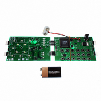
DEMO BOARD LED DIMMER
Manufacturer
NXP Semiconductors
Datasheet
1.OM6279598.pdf
(45 pages)
Specifications of OM6279,598
Main Purpose
Lighting, RGB LED Controller
Embedded
Yes, MCU, 8-Bit
Utilized Ic / Part
PCA9564PW, PCA9555PW, PCA9531PW, PCA9533DP/01
Primary Attributes
I2C Bus Controller, 1 8-Bit GPIO, 1 8-Bit LED Dimmer
Secondary Attributes
Different Demonstration Programs Through MCU
Lead Free Status / RoHS Status
Not applicable / Not applicable
Other names
568-4003
935283363598
935283363598


Philips Semiconductors
}
9397 750 14062
Application note
}
GPIO_Polling_On = 0;
Buffer3[1]
Message1.address = PCA9531_M_WR;
Message1.nrBytes = 3;
Buffer1[0]
Buffer1[1]
Buffer1[2]
I2C_Write(&Message1);
}
if (Buffer3[0] == 0xDF)
{
}
Buffer3[0] = 0xFF;
}
if (Battery_Level == 0x40)
{
}
if (Battery_Level == 0x00)
{
}
Battery_Level
Message1.address = PCA9531_M_WR;
Message1.nrBytes = 6;
Buffer1[0]
Buffer1[1]
Buffer1[2]
Buffer1[3]
Buffer1[4]
Buffer1[5]
I2C_Write(&Message1);
Buffer1[0]
Buffer1[1]
Buffer1[2]
Buffer1[3]
Buffer1[4]
Buffer1[5]
I2C_Write(&Message1);
Message1.address = PCA9531_M_WR; // PCA9531 Misc
Message1.nrBytes = 6;
Buffer1[0]
Buffer1[1]
Buffer1[2]
Buffer1[3]
Buffer1[4]
Buffer1[5]
I2C_Write(&Message1);
Message1.address = PCA9531_M_WR; // PCA9531 Misc
Message1.nrBytes = 6;
Buffer1[0]
Buffer1[1]
Buffer1[2]
Buffer1[3]
Buffer1[4]
Buffer1[5]
I2C_Write(&Message1);
= 0xFF;
= 0x15;
= 0x00;
= 0x30;
= 0xFF;
= 0x12;
= Battery_Level - 0x10; // High Duty Cycle when Battery charge > 50%
= 0x97;
= 0x08;
= 0x55;
= 0x32;
= 0x12;
= 0x80;
= 0x97;
= 0x08;
= 0x50;
= 0x3A;
= 0x12;
= 0x10;
= 0x97;
= 0x08;
= 0x40;
= 0x38;
= 0x12;
= 0x01;
= 0x97;
= 0x08;
= 0x00;
= 0x38;
// subaddress = 0x02
// RG (Orange) LED shorter duty cycle
// default prescaler pwm1 = 1 Hz
// default duty cycle for pwm1 = 50%
// LD5 and LD6 now off
// RG LED Green and Red blinking at BR0 (Orange)
// subaddress = 0x02
// RG (Red only) LED even shorter duty cycle
// default prescaler pwm1 = 1 Hz
// default duty cycle for pwm1 = 50%
// LD5, LD6 and LD7 now off
// RG LED Green and Red blinking at BR0
// subaddress = 0x02
// Duty Cycle = 0x01 --> Red LED actually almost off
// default prescaler pwm1 = 1 Hz
// default duty cycle for pwm1 = 50%
// LD5, LD6, LD7 and LD8 now off
// RG LED Green and Red blinking at BR0
// Reset the simulation and recharge completly the battery (Key 6 pushed)
// PCA9531 Misc
// subaddress = 0x02
// default prescaler pwm1 = 1 Hz
// default duty cycle for pwm1 = 50%
// LD5 to LD8 on --> Indicate battery fully charged
// RG LED Green blinking at BR0
// Clear Key 3 pushed
// Disable PCA9555 polling option (see GPIO_Interrupt_Handler function)
// PCA9531 Misc
// LD5 to LD8 off
Rev. 01 — 7 January 2005
© Koninklijke Philips Electronics N.V. 2005. All rights reserved.
LED dimmer demoboard
AN10315
36 of 45
Related parts for OM6279,598
Image
Part Number
Description
Manufacturer
Datasheet
Request
R

Part Number:
Description:
Display Modules & Development Tools LED EVAL Board
Manufacturer:
NXP Semiconductors

Part Number:
Description:
NXP Semiconductors designed the LPC2420/2460 microcontroller around a 16-bit/32-bitARM7TDMI-S CPU core with real-time debug interfaces that include both JTAG andembedded trace
Manufacturer:
NXP Semiconductors
Datasheet:

Part Number:
Description:
NXP Semiconductors designed the LPC2458 microcontroller around a 16-bit/32-bitARM7TDMI-S CPU core with real-time debug interfaces that include both JTAG andembedded trace
Manufacturer:
NXP Semiconductors
Datasheet:
Part Number:
Description:
NXP Semiconductors designed the LPC2468 microcontroller around a 16-bit/32-bitARM7TDMI-S CPU core with real-time debug interfaces that include both JTAG andembedded trace
Manufacturer:
NXP Semiconductors
Datasheet:
Part Number:
Description:
NXP Semiconductors designed the LPC2470 microcontroller, powered by theARM7TDMI-S core, to be a highly integrated microcontroller for a wide range ofapplications that require advanced communications and high quality graphic displays
Manufacturer:
NXP Semiconductors
Datasheet:
Part Number:
Description:
NXP Semiconductors designed the LPC2478 microcontroller, powered by theARM7TDMI-S core, to be a highly integrated microcontroller for a wide range ofapplications that require advanced communications and high quality graphic displays
Manufacturer:
NXP Semiconductors
Datasheet:
Part Number:
Description:
The Philips Semiconductors XA (eXtended Architecture) family of 16-bit single-chip microcontrollers is powerful enough to easily handle the requirements of high performance embedded applications, yet inexpensive enough to compete in the market for hi
Manufacturer:
NXP Semiconductors
Datasheet:
Part Number:
Description:
The XA-S3 device is a member of Philips Semiconductors? XA(eXtended Architecture) family of high performance 16-bitsingle-chip microcontrollers
Manufacturer:
NXP Semiconductors
Datasheet:

Part Number:
Description:
The NXP BlueStreak LH75401/LH75411 family consists of two low-cost 16/32-bit System-on-Chip (SoC) devices
Manufacturer:
NXP Semiconductors
Datasheet:
Part Number:
Description:
The NXP LPC3130/3131 combine an 180 MHz ARM926EJ-S CPU core, high-speed USB2
Manufacturer:
NXP Semiconductors
Datasheet:
Part Number:
Description:
The NXP LPC3141 combine a 270 MHz ARM926EJ-S CPU core, High-speed USB 2
Manufacturer:
NXP Semiconductors
Part Number:
Description:
The NXP LPC3143 combine a 270 MHz ARM926EJ-S CPU core, High-speed USB 2
Manufacturer:
NXP Semiconductors

Part Number:
Description:
The NXP LPC3152 combines an 180 MHz ARM926EJ-S CPU core, High-speed USB 2
Manufacturer:
NXP Semiconductors
Part Number:
Description:
The NXP LPC3154 combines an 180 MHz ARM926EJ-S CPU core, High-speed USB 2
Manufacturer:
NXP Semiconductors