IS-DEV KIT-7 NKK Switches, IS-DEV KIT-7 Datasheet - Page 5
IS-DEV KIT-7
Manufacturer Part Number
IS-DEV KIT-7
Description
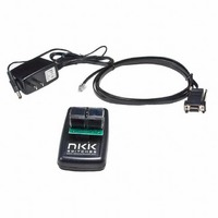
KIT DEV FOR OLED SWITCH
Manufacturer
NKK Switches
Series
SmartSwitch™r
Datasheet
1.IS-DEV_KIT-7D.pdf
(24 pages)
Specifications of IS-DEV KIT-7
Main Purpose
Switches with Programmable Display
Embedded
Yes, ASIC
Utilized Ic / Part
ISC15ANP4
Primary Attributes
2 OLED Switches, PC Board with Flash Memory
Secondary Attributes
Power and Programming Connections
Description/function
SMARTSWITCH Development Kit
For Use With
360-2431 - SERIAL CBL RJ11-DB9 FOR DEV KIT360-2430 - POWER SUPPLY 240VAC FOR DEV KIT360-2429 - POWER SUPPLY 120VAC FOR DEV KIT
Lead Free Status / RoHS Status
Not applicable / Not applicable
For Use With/related Products
Smart Switch - OLED
Other names
360-2339


7850 East Gelding Drive • Scottsdale, AZ 85260-3420
Illustration 2 shows a simple loop where images at addresses 0041H through 0057H are shown in sequence for
two seconds each and will loop continuously until the switch associated with that particular address is pressed
or the loop ends. When that switch is pressed the controller will set the left hand switch to address 0001H and
the right hand switch to address 006AH. If the loop ends before the switch is pressed the left switch will go to
address 0059H and the right switch will go to address 005AH.
If SW1 and/or SW2 for the ending addresses are 0000H the loop will start again. Loops can overlap where, for
instance, the left switch starts at address 0001H and ends at 0005H while the right switch starts at 0002H and
ends at 0006H. The two loops will not interfere with each other.
Timers Operation:
Each switch has an independent timer; timer1 and timer2. Each timer value is the product of the two user
defined variables T1 and T2 of the attributes. The formula for the timer value in millisecond is:
Each of these variables can have a value between 01H to FFH (1 to 255). The timer for a given switch will
be disabled if the T1 value is set to zero. For T2 the zero value is defined as 256. Pressing either switch will
reset the timers for both switches. Holding down either switch will prevent both timers from running. The
CL01 Intelligent Controller Users Manual B.doc
The timer value in ms= (T1)x(T2)
…
Start Image
…
Ending Image
…
…
Start Image
Next Image
…
Next Image
Ending Image
…
Toll Free 1.877.2BUYNKK (877.228.9655) • Phone 480.991.0942 • Fax 480.998.1435
CL01 Intelligent Controller Users Manual
…
0001
…
0003
…
Address
Address
…
0041
0042
…
0056
0057
…
Illustration 1, Start and Ending Addresses for Switch A
www.nkkswitches.com • Email engineering@nkkswitches.com
…
Left switch’s
future address
when switch A
is pressed.
…
Left switch’s
future address
when end of
loop
…
Illustration 2, Simple Image Loop
SW1
SW1
…
0001
0000
…
0000
0059
…
Actions Addresses
Actions Addresses
…
Right switch’s
future address
when switch A
is pressed.
…
Right switch’s
future address
when end of
loop
…
SW2
…
006A
0000
…
0000
005A
…
SW2
EP1
…
0057
0000
…
0000
0000
…
…
Ending
Address
(0003)
…
Don’t
care
…
EP1
T1
…
7D
00
…
00
00
…
…
milli-
seconds
…
Don’t
care
…
T1
T2
…
14
00
…
00
00
…
…
milli-
seconds
…
Don’t
care
…
T2
Page 5 of 24
0110
Related parts for IS-DEV KIT-7
Image
Part Number
Description
Manufacturer
Datasheet
Request
R

Part Number:
Description:
SMARTSWITCH DEVELOPMENT KIT 5C
Manufacturer:
NKK Switches
Datasheet:

Part Number:
Description:
KIT DEV FOR LCD 64X32 SWITCH
Manufacturer:
NKK Switches
Datasheet:

Part Number:
Description:
KIT DEV LCD 64X32 COMPACT SWITCH
Manufacturer:
NKK Switches
Datasheet:

Part Number:
Description:
KIT DEV FOR OLED DISPLAY
Manufacturer:
NKK Switches
Datasheet:

Part Number:
Description:
BOARD DEV 2RGB SW FLASH & PROGR
Manufacturer:
NKK Switches
Datasheet:

Part Number:
Description:
KIT DEV FOR LCD 64X32 DISPLAY
Manufacturer:
NKK Switches
Datasheet:

Part Number:
Description:
SMARTSWITCH DEVELOPMENT KIT 1
Manufacturer:
NKK Switches
Datasheet:

Part Number:
Description:
SMARTSWITCH DEVELOPMENT KIT 2
Manufacturer:
NKK Switches
Datasheet:

Part Number:
Description:
SMARTSWITCH DEVELOPMENT KIT 5
Manufacturer:
NKK Switches
Datasheet:

Part Number:
Description:
SMARTSWITCH DEVELOPMENT KIT 8
Manufacturer:
NKK Switches
Datasheet:

Part Number:
Description:
LED Displays PROGRAMMABLE SWITCH
Manufacturer:
NKK Switches

Part Number:
Description:
ON-OFF PLATE - SERIES -EMP
Manufacturer:
NKK Switches
Datasheet:

Part Number:
Description:
WRENCH SOCKET FOR KB SERIES PB
Manufacturer:
NKK Switches
Datasheet:

Part Number:
Description:
SWITCH TOGGLE DPST 25A SLDR 5PCS
Manufacturer:
NKK Switches
Datasheet:

Part Number:
Description:
SWITCH TOGGLE DPDT 15A SLDR 5PC
Manufacturer:
NKK Switches
Datasheet: