IS-DEV KIT-7 NKK Switches, IS-DEV KIT-7 Datasheet - Page 8
IS-DEV KIT-7
Manufacturer Part Number
IS-DEV KIT-7
Description
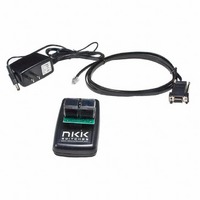
KIT DEV FOR OLED SWITCH
Manufacturer
NKK Switches
Series
SmartSwitch™r
Datasheet
1.IS-DEV_KIT-7D.pdf
(24 pages)
Specifications of IS-DEV KIT-7
Main Purpose
Switches with Programmable Display
Embedded
Yes, ASIC
Utilized Ic / Part
ISC15ANP4
Primary Attributes
2 OLED Switches, PC Board with Flash Memory
Secondary Attributes
Power and Programming Connections
Description/function
SMARTSWITCH Development Kit
For Use With
360-2431 - SERIAL CBL RJ11-DB9 FOR DEV KIT360-2430 - POWER SUPPLY 240VAC FOR DEV KIT360-2429 - POWER SUPPLY 120VAC FOR DEV KIT
Lead Free Status / RoHS Status
Not applicable / Not applicable
For Use With/related Products
Smart Switch - OLED
Other names
360-2339


7850 East Gelding Drive • Scottsdale, AZ 85260-3420
Detailed Explanation of Operation Step 6
Step 6A: If switch 1 is pressed then:
Step 6B: If switch 2 is pressed then:
CL01 Intelligent Controller Users Manual B.doc
H. If there is update flag for switch 2 is set, process it.
I. Checks the host communication buffer for data. If there is data, process them. (For detail see
J. Go to step 6 A.
1. Transmit 81H to host if flag is enabled.
2. If switch 1 action address for switch 1 is not equal zero and the attribute for the location is
3. If switch 1 action address for switch 1 is equal zero or the attribute for the location is not
4. If switch 1 action address for switch 2 is not equal zero and the attribute for the location is
5. If switch 1 action address for switch 2 is equal zero or the attribute for the location is not
1. Transmit 82H to host if flag is enabled.
2. If switch 2 action address for switch 1 is not equal zero and the attribute for the location is
3. If switch 2 action address for switch 1 is equal zero or the attribute for the location is not
Communication Protocol)
programmed then:
a. Start address for switch 1 = switch 1 action address for switch 1.
b. Current address for switch 1 = switch 1 action address for switch 1.
c. Get the attributes and put the values for switch 1 action address for switch 1, switch 1 action
d. Set update flag for switch 1.
programmed then take no action.
programmed then:
a. Start address for switch 2 = switch 1 action address for switch 2.
b. Current address for switch 2 = switch 1 action address for switch 2.
c. Get the attributes and put the values for switch 2 action address for switch 1, switch 2 action
d. Set update flag for switch 2.
programmed then take no action.
programmed then:
a. Start address for switch 1 = switch 2 action address for switch 1.
b. Current address for switch 1 = switch 2 action address for switch 1.
c. Get the attributes and put the values for switch 1 action address for switch 1, switch 1 action
d. Set update flag for switch 1.
programmed then take no action.
address for switch 2, end address for switch 1 and timers for switch 1.
address for switch 2, end address for switch 2 and timers for switch 2.
address for switch 2, end address for switch 1 and timers for switch 1.
Toll Free 1.877.2BUYNKK (877.228.9655) • Phone 480.991.0942 • Fax 480.998.1435
CL01 Intelligent Controller Users Manual
www.nkkswitches.com • Email engineering@nkkswitches.com
Page 8 of 24
0110
Related parts for IS-DEV KIT-7
Image
Part Number
Description
Manufacturer
Datasheet
Request
R

Part Number:
Description:
SMARTSWITCH DEVELOPMENT KIT 5C
Manufacturer:
NKK Switches
Datasheet:

Part Number:
Description:
KIT DEV FOR LCD 64X32 SWITCH
Manufacturer:
NKK Switches
Datasheet:

Part Number:
Description:
KIT DEV LCD 64X32 COMPACT SWITCH
Manufacturer:
NKK Switches
Datasheet:

Part Number:
Description:
KIT DEV FOR OLED DISPLAY
Manufacturer:
NKK Switches
Datasheet:

Part Number:
Description:
BOARD DEV 2RGB SW FLASH & PROGR
Manufacturer:
NKK Switches
Datasheet:

Part Number:
Description:
KIT DEV FOR LCD 64X32 DISPLAY
Manufacturer:
NKK Switches
Datasheet:

Part Number:
Description:
SMARTSWITCH DEVELOPMENT KIT 1
Manufacturer:
NKK Switches
Datasheet:

Part Number:
Description:
SMARTSWITCH DEVELOPMENT KIT 2
Manufacturer:
NKK Switches
Datasheet:

Part Number:
Description:
SMARTSWITCH DEVELOPMENT KIT 5
Manufacturer:
NKK Switches
Datasheet:

Part Number:
Description:
SMARTSWITCH DEVELOPMENT KIT 8
Manufacturer:
NKK Switches
Datasheet:

Part Number:
Description:
LED Displays PROGRAMMABLE SWITCH
Manufacturer:
NKK Switches

Part Number:
Description:
ON-OFF PLATE - SERIES -EMP
Manufacturer:
NKK Switches
Datasheet:

Part Number:
Description:
WRENCH SOCKET FOR KB SERIES PB
Manufacturer:
NKK Switches
Datasheet:

Part Number:
Description:
SWITCH TOGGLE DPST 25A SLDR 5PCS
Manufacturer:
NKK Switches
Datasheet:

Part Number:
Description:
SWITCH TOGGLE DPDT 15A SLDR 5PC
Manufacturer:
NKK Switches
Datasheet: