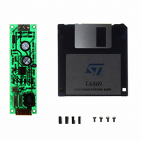
EVAL6569 STMicroelectronics, EVAL6569 Datasheet - Page 5

EVAL6569
Manufacturer Part Number
EVAL6569
Description
BOARD EVAL LIGHTING L6569
Manufacturer
STMicroelectronics
Type
Charge Pumpsr
Datasheet
1.EVAL6569.pdf
(14 pages)
Specifications of EVAL6569
Mfg Application Notes
L6569, AN880 App Note
Main Purpose
Lighting, Ballast Control
Embedded
No
Utilized Ic / Part
L6569
Primary Attributes
18 W, Optimized for a CF18DT/E/830, 120 or 230 VAC
Secondary Attributes
Preheating Done with a PTC
Input Voltage
230 V
Product
Power Management Modules
Supply Current
0.17 A
Lead Free Status / RoHS Status
Lead free / RoHS Compliant
For Use With/related Products
L6569
Other names
497-4738
Figure 9. L6569 driver protection against voltage spikes.
The auxiliary supply of the converter
The circuit consumption is defined by the MOS-
FETs gate charge, the I.C. consumption, the os-
cillator, and the shunt regulator. Several circuits
are possible.
In many applications a snubber is used to reduce
the dissipation in the MOSFETs. When this snub-
ber is used in conjunction with a start up resistor
(R
achieved almost for free.
At start up the I.C. is consuming 150 A, and there-
fore only a small supply resistor is required. During
operation the capacitor provides the supply current.
To avoid cross conduction, the capacitance is lim-
ited by the driver dead time T
tive supply current I
last this circuit easily supplies the required
operating current. Using a CF18DT lamp ( I
mA) the required capacitance is 470 pF on 230 Vac
line. At 50 kHz the average capacitive current is 6
mA, as described in appendix B.
When the required driver current is higher than 10
Figure 10: Non dissipative auxiliary supply using the transistor snubber.
S
in Figure 10), a non dissipative supply is
C
is also limited.For a CFL bal-
1mA WHEN STARTING
BV
L6569
D
. Hence the capaci-
OUT
> 600V
15V
220k
Rs
Cs
L
> 230
L6569
bootstrap
circuit
V
6 mA WHEN 50 kHz SWITCHING
C
OUT
OFF
mA, a secondary winding on the resonant choke
is an easy supply alternative.
The ballast shutdown
The L6569 allows several ways (see figg. 11, 12
and 13) to shutdown the ballast [4]: by acting on
the C
MOSFET or by acting on the V
the Under Voltage Lock Out.
Acting on C
be used, and it has to be: R
When the shutdown is realized acting on Vs pin,
(see fig. 12) a limiting resistor Rs must be used to
slow down the discharge of the supply filter Cs.
The constant time of the discharge must be
greater than 10 periods of the switching fre-
quency:
Connecting the C
oscillator, and the lower MOSFET will remain ON.
Therefore
ON
470 pF
H.V.+
F
input oscillator pin to turn off the upper
F
the
(Fig. 11) a limiting resistor R
310 V
AN880 APPLICATION NOTE
F
bootstrap
R
S
pin to ground GND stops the
I
C
s
10
L
f
sw
capacitor
C
F
S
> 1 s.
supply pin with
remains
L
has to
5/14


