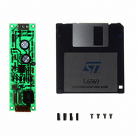
EVAL6569 STMicroelectronics, EVAL6569 Datasheet - Page 7

EVAL6569
Manufacturer Part Number
EVAL6569
Description
BOARD EVAL LIGHTING L6569
Manufacturer
STMicroelectronics
Type
Charge Pumpsr
Datasheet
1.EVAL6569.pdf
(14 pages)
Specifications of EVAL6569
Mfg Application Notes
L6569, AN880 App Note
Main Purpose
Lighting, Ballast Control
Embedded
No
Utilized Ic / Part
L6569
Primary Attributes
18 W, Optimized for a CF18DT/E/830, 120 or 230 VAC
Secondary Attributes
Preheating Done with a PTC
Input Voltage
230 V
Product
Power Management Modules
Supply Current
0.17 A
Lead Free Status / RoHS Status
Lead free / RoHS Compliant
For Use With/related Products
L6569
Other names
497-4738
THE LAMP SEEN BY THE ELECTRONIC DE-
SIGNER
The lamp equivalent impedance
The compact fluorescent lamps are specified at
25 kHz (IEC 929). The MOSFETs and the L6569
allow to increase the switching frequency, but the
sensitivity of the lamp to the frequency needs to
be analyzed.
A few samples of the CF18DT/E lamp were
tested by varying the frequency and the current of
the lamp. The figure 14 shows the lamp imped-
ance versus its current as it varies from 0.1A to
0.23A with 5 frequencies from 25 to 150 kHz
(T
Figure 14: Variation of the lamp impedance
From the tests the impedance appears insensitive
to the frequency for such lamps. The specified im-
pedance might be valid for higher frequency op-
eration. The relative lamp light output was meas-
ured as proposed in reference [5]. The light flux
increases slightly in that frequency range, but can
be considered constant.
Obviously the impedance is sensitive to the cur-
rent with a negative coefficient, and the ballast
operates with a non linear impedance [6]. When
current is half the nominal one, the impedance is
2.6 times higher, and the voltage is only 25%
higher (see figure 15).
Figure 15: Variation of the average impedance
R lamp (Ohms)
1200
1000
R (Ohms)
1200
800
600
400
200
900
600
300
AMB
0
0.05
0
0.05
= 25°C).
0.1
versus its current for several
switching frequencies.
and voltage of the lamp
0.1
0.15
I lamp (A)
0.15
I (A)
0.2
0.2
0.25
0.25
U (V)
200
150
100
50
0
0.3
100 kHz
150 kHz
25 kHz
50 kHz
Rlamp
Vlamp
The preheat
Preheat techniques are used in CFL ballasts to
reduce the ignition lamp voltage. During this
phase the lamp is characterized by a high imped-
ance that forces the electrical conduction through
the preheat filaments. These filaments initially
have a low resistance that will increase by 5 times
during the preheat. The preheat typically lasts
from 400 ms to 1 s, and is achieved by controlling
either the current or the voltage of the filaments.
For a current control the filaments are in series
with the resonant network as shown on figure
16a. When the inverter frequency is constant, a
positive temperature coefficient thermistor (PTC)
in parallel with the lamp achieves the task by ad-
justing both the filament current and the preheat
duration. The board uses a 150
8.2 nF capacitors. The preheat lasts 0.8s and the
filament current is 0.45 Arms. The PTC is a cheap
device, but it is dissipative and works only once at
power-up.
Figure 16: Basic preheat current control diagram
The preheat can be achieved with a filament volt-
age control. The filaments are supplied by two
auxiliary windings of the resonant choke as
shown figure 17a. During the preheat the L6569
frequency is increased, and the choke operates
(A)
(B)
I
CTL
(a); preheat filament energy curve (b)
AN880 APPLICATION NOTE
E
If
I
CTL
PTC with two
E=R.I²
LAMP
t
7/14


