EVAL6206N STMicroelectronics, EVAL6206N Datasheet - Page 17
EVAL6206N
Manufacturer Part Number
EVAL6206N
Description
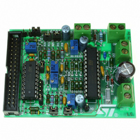
EVAL BOARD FOR L6206N DIP
Manufacturer
STMicroelectronics
Specifications of EVAL6206N
Mfg Application Notes
PractiSPIN AppNote
Design Resources
EVAL6206N/6206N Gerber Files EVAL6206N Schematic/Bill of Materials
Main Purpose
Power Management, H Bridge Driver (Internal FET)
Embedded
No
Utilized Ic / Part
L6205N DIP
Primary Attributes
Dual Full-Bridge (H-Bridge), 2.8A (5.6A Peak). 8 ~ 52 V, 0.3 Ohm
Secondary Attributes
Non-Inverting, Can be Paralleled
Architecture
Analog
Applications
Motor Control
Processor To Be Evaluated
L6206
For Use With
497-4138 - EVALUATION BOARD PRACTISPIN
Lead Free Status / RoHS Status
Lead free / RoHS Compliant
Other names
497-5487


UM0240
6.2
6.3
RS-232 Interface
The RS-232 interface can be used as a communication channel to a PC running control
software. It consists of female connector J10, where only three pins are connected with the
DCE connections:
●
●
●
So the connection to a PC RS-232 port (DTE) must be done by a direct cable connecting:
●
●
RS-232 signals are obtained and adapted to 5V circuitry by means of the ST232 multi-
channel RS-232 driver and receiver connected to two general purpose IOs (PD7 and PF0).
The microcontroller emulates the RS-232 interface by software.
The ST232 can be powered down, to reduce power consumption when RS232 interface is
not used, by opening jumper J11. In this case, two microcontroller pins (#44 and #52) can
be used as General Purpose IOs (PD7 and PF0).
Motor control
Communication with Motor Control boards is possible through connector J7. This is a 34-pin
connector providing the following signals, in the EVAL6207N case:
Table 2.
Pin number
5 → Ground
3 → DCE TX
2 → DCE RX
DTE pin3 to DCE pin 3
DTE pin 2 to DCE pin 2
11
23
27
29
31
33
10
14
20
22
26
1
3
7
4
8
Motor control interface pins
Signal name
VCC_REF
SENSE_A
SENSE_B
LIMIT_A
LIMIT_B
LIMIT_B
LIMIT_A
Ground
VREFB
VREFA
RCA
ENA
+5V
IN1
IN4
IN3
5V Supply Voltage
Channel A Sense Voltage
Channel B Sense Voltage
5V Supply Voltage
Ground
Channel A Over Current Flag
Channel B Over Current Flag
Ch A PWM Current Control Ref Voltage
Ch B PWM Current Control Ref Voltage
Channel A Over Current Flag
Channel B Over Current Flag
Ch A RC Monostable Voltage
Ch A Enable Signal
Ch A Input 1
Ch B Input 2
Ch B Input 1
Description
Interfaces and connectors
Generated by
EVAL6207N
EVAL6207N
EVAL6207N
EVAL6207N
EVAL6207N
EVAL6207N
EVAL6207N
EVAL6207N
MCU
MCU
MCU
MCU
MCU
MCU
MCU
17/39
Related parts for EVAL6206N
Image
Part Number
Description
Manufacturer
Datasheet
Request
R

Part Number:
Description:
STMicroelectronics [RIPPLE-CARRY BINARY COUNTER/DIVIDERS]
Manufacturer:
STMicroelectronics
Datasheet:
Part Number:
Description:
STMicroelectronics [LIQUID-CRYSTAL DISPLAY DRIVERS]
Manufacturer:
STMicroelectronics
Datasheet:

Part Number:
Description:
BOARD EVAL FOR MEMS SENSORS
Manufacturer:
STMicroelectronics
Datasheet:
Part Number:
Description:
NPN TRANSISTOR POWER MODULE
Manufacturer:
STMicroelectronics
Datasheet:
Part Number:
Description:
TURBOSWITCH ULTRA-FAST HIGH VOLTAGE DIODE
Manufacturer:
STMicroelectronics
Datasheet:
Part Number:
Description:
Manufacturer:
STMicroelectronics
Datasheet:
Part Number:
Description:
DIODE / SCR MODULE
Manufacturer:
STMicroelectronics
Datasheet:
Part Number:
Description:
DIODE / SCR MODULE
Manufacturer:
STMicroelectronics
Datasheet:
Part Number:
Description:
Search -----> STE16N100
Manufacturer:
STMicroelectronics
Datasheet:
Part Number:
Description:
Search ---> STE53NA50
Manufacturer:
STMicroelectronics
Datasheet:
Part Number:
Description:
NPN Transistor Power Module
Manufacturer:
STMicroelectronics
Datasheet:
Part Number:
Description:
DIODE / SCR MODULE
Manufacturer:
STMicroelectronics
Datasheet: