EVAL6206N STMicroelectronics, EVAL6206N Datasheet - Page 27
EVAL6206N
Manufacturer Part Number
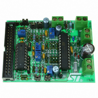
EVAL6206N
Description
EVAL BOARD FOR L6206N DIP
Manufacturer
STMicroelectronics
Specifications of EVAL6206N
Mfg Application Notes
PractiSPIN AppNote
Design Resources
EVAL6206N/6206N Gerber Files EVAL6206N Schematic/Bill of Materials
Main Purpose
Power Management, H Bridge Driver (Internal FET)
Embedded
No
Utilized Ic / Part
L6205N DIP
Primary Attributes
Dual Full-Bridge (H-Bridge), 2.8A (5.6A Peak). 8 ~ 52 V, 0.3 Ohm
Secondary Attributes
Non-Inverting, Can be Paralleled
Architecture
Analog
Applications
Motor Control
Processor To Be Evaluated
L6206
For Use With
497-4138 - EVALUATION BOARD PRACTISPIN
Lead Free Status / RoHS Status
Lead free / RoHS Compliant
Other names
497-5487


UM0240
10.2
10.2.1
10.2.2
Applications
Beside the DFU, application-specific firmware has been developed to enable the Industrial
Communication Board to control and communicate with different application boards.
Power Line Communication (PLC)
Dedicated firmware is available to use in conjunction with Power Line Communication (PLC)
Boards.
Power Line Communication Boards, based on ST7538 and ST7540 power line transceivers,
allow communication over the main AC voltage plugs at a low baud rate. These products are
designed for Home Automation, Building Automation, Automatic Meter Reading, and Street
Lighting control applications as well as other applications that do not require a broad band
communication link.
The PLC dedicated firmware performs basic functions such as:
●
●
●
●
Motor control
Dedicated FW is available to control different Motor Control boards. In operating a stepper
motor system one of the most common requirements is to execute a relative move. The
move is usually specified as a fixed number of basic motor steps in the clockwise or counter-
clockwise direction. It is common practice to execute this move along a trapezoidal shaped
velocity vs. time profile. FW calculate moving profiles to be used as command signals to
move the controlled motor in a defined position. Given the move distance, acceleration,
deceleration, and peak speed requirement, a profile can be determined. The control
structure is designed such that the velocity and acceleration/deceleration rate can be
changed at will, the task of pre-calculating the velocity profile boils down to determining the
position values where operation switches from acceleration to constant speed and then from
constant speed to deceleration. Execution time for these calculations is not critical since
they are done only once per move and are completed before the move begins. The heart of
the stepper motor control mechanism is the 20-kHz interrupt. This interrupt invokes an
Interrupt Service Routine (ISR) which executes repeatedly on a fixed time interval of 50
microseconds called TICK.
The ISR calculates real time values for velocity and position given the commanded
acceleration (or deceleration) and the present values for velocity and position.
A complete description of algorithms and formulas used by the FW is present in AN2044
Operating principles for Practispin Stepper Motor Motion Control.
Program transceiver control parameters: channel frequency, baud rate and so on (for
more options see the transceiver datasheet or the dedicated firmware application
note).
Transmit a user-defined data stream through the AC line either as single or multiple
repetition.
Receive data from the AC line either in free-running mode or after synchronization with
a programmable known sequence (frame header).
Perform a communication channel reliability test with a Client-Server application that
can calculate the reachability of each node by sending messages and retrieving
answers. This function implements a Forward Error Correction algorithm to detect if the
network under test requires a FEC algorithm or not.
Firmware
27/39
Related parts for EVAL6206N
Image
Part Number
Description
Manufacturer
Datasheet
Request
R

Part Number:
Description:
STMicroelectronics [RIPPLE-CARRY BINARY COUNTER/DIVIDERS]
Manufacturer:
STMicroelectronics
Datasheet:
Part Number:
Description:
STMicroelectronics [LIQUID-CRYSTAL DISPLAY DRIVERS]
Manufacturer:
STMicroelectronics
Datasheet:

Part Number:
Description:
BOARD EVAL FOR MEMS SENSORS
Manufacturer:
STMicroelectronics
Datasheet:
Part Number:
Description:
NPN TRANSISTOR POWER MODULE
Manufacturer:
STMicroelectronics
Datasheet:
Part Number:
Description:
TURBOSWITCH ULTRA-FAST HIGH VOLTAGE DIODE
Manufacturer:
STMicroelectronics
Datasheet:
Part Number:
Description:
Manufacturer:
STMicroelectronics
Datasheet:
Part Number:
Description:
DIODE / SCR MODULE
Manufacturer:
STMicroelectronics
Datasheet:
Part Number:
Description:
DIODE / SCR MODULE
Manufacturer:
STMicroelectronics
Datasheet:
Part Number:
Description:
Search -----> STE16N100
Manufacturer:
STMicroelectronics
Datasheet:
Part Number:
Description:
Search ---> STE53NA50
Manufacturer:
STMicroelectronics
Datasheet:
Part Number:
Description:
NPN Transistor Power Module
Manufacturer:
STMicroelectronics
Datasheet:
Part Number:
Description:
DIODE / SCR MODULE
Manufacturer:
STMicroelectronics
Datasheet: