M3A-0033 Renesas Electronics America, M3A-0033 Datasheet - Page 8
M3A-0033
Manufacturer Part Number
M3A-0033
Description
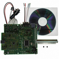
DEV EVALUATION BOARD FOR M66291G
Manufacturer
Renesas Electronics America
Datasheet
1.M3A-0033.pdf
(39 pages)
Specifications of M3A-0033
Main Purpose
USB Controller
Embedded
*
Utilized Ic / Part
M66291
Primary Attributes
*
Secondary Attributes
*
Lead Free Status / RoHS Status
Contains lead / RoHS non-compliant


3.4 Jumper Switch Setup (JPx)
M66291GP Evaluation Board
Jumper switches setup of M3A-0033 are shown in Table 3-2.
Table 3-2 Jumper switch setup of M3A-0033
Note1. Please refer to “Chapter 7” about programming to built-in flash memory.
Note2. Please refer to section “6.1” for details.
Note3. Please refer to section “6.2” for details.
Note4. Please refer to section “6.3” for details.
Caution! : Please don’t use JP7, JP8, JP10, JP11, JP14, JP15, JP16, JP17, and JP19.
JP
JP1
JP2
JP3
JP4
JP5
JP6
JP9
JP12
JP13
JP18
JP20
JP21
Name
Flash memory
programming
setup (1)
setup (2)
Flash memory
programming
setup (3)
Flash memory
programming
setup (4)
Power supply origin
selection
Supply voltage
selection :
V
IOVCC of
M66291GP
*INT2 of M16C/80
connection
UART0 TXD
enable
UART0 RXD
enable
*Dreq0 enable
UART0 RTS
enable
UART0 CTS
enable
Flash memory
programming
In case of connecting M3A-0029B, set JP6 to “3.3V” fixation, and JP9 is invalid.
CC
of M16C/80,
Contents
Short: Programming to internal flash memory of M16C/80 by FlashStart. (Note1)
Open: Debugging by KD308 or running user programmed by FlashStart(Default)
Flash: Programming to internal flash memory of M16C/80 by FlashStart. (Note1)
Normal: Debugging by KD308 or running user programmed by FlashStart
Select power supply origin.
“EX5V”
“Vbus”
Select supply voltage to V
(5.0V/3.3V). Usually, please set to "3.3V". (Note2)
“3.3V”
“5.0V”
Open: *INT2 of M16C/80 open (Default)
“*Dreq1”
GND: UART0 TXD is disabled. (Default)
TXD0: UART0 TXD is enabled.
(Note4)
Open: UART0 RXD is disabled. (Default)
Short: UART0 RXD is enabled.
(Note4)
Set up when the DMA transfer by using *Dreq0.
Usually, please set to “OPEN”. (Note3)
Jumper
GND: UART0 RTS is disabled. (Default)
P80 : UART0 RTS is enabled.
(Note4)
Open: UART0 CTS is disabled. (Default)
Short: UART0 CTS is enabled.
(Note4)
(Regulated DC power supply / Vbus power supply on USB line)
Usually, please set to "EX5V". (Note2)
short-circuited
RTS pin of CN6 is connected to GND pin of M16C/80 (via MAX3241E)
RTS pin of CN6 is connected to P80 pin of M16C/80 (via MAX3241E)
(Default)
- 4 -
Select regulated DC power supply.
Select Vbus.
Supply 3.3V to V
M66291GP.
Supply 5.0V to V
M66291GP.
*Dreq1 pin of M66291GP is assigned to *INT2 pin of
M16C/80. (Note3)
*Dreq0 pin of M66291GP is assigned to *INT1 pin of
M16C/80.
CC
of M16C/80, and IOVCC of M66291GP
CC
CC
of M16C/80 and IOVCC of
of M16C/80 and IOVCC of
M3A-0033
Related parts for M3A-0033
Image
Part Number
Description
Manufacturer
Datasheet
Request
R

Part Number:
Description:
DEV EVALUATION BOARD FOR M66592
Manufacturer:
Renesas Electronics America
Part Number:
Description:
DEV EVALUATION KIT FOR M66596
Manufacturer:
Renesas Electronics America
Datasheet:
Part Number:
Description:
DEV EVALUATION BOARD FOR M66591G
Manufacturer:
Renesas Electronics America
Part Number:
Description:
M35054/M35055-XXXSP/FP EVAL BOAR
Manufacturer:
Renesas Electronics America
Part Number:
Description:
DEV M35070/71-XXXFP,M35047-XXXFP
Manufacturer:
Renesas Electronics America
Part Number:
Description:
DEV EVALUATION BOARD 38K0/38K2 G
Manufacturer:
Renesas Electronics America

Part Number:
Description:
KIT STARTER FOR M16C/29
Manufacturer:
Renesas Electronics America
Datasheet:

Part Number:
Description:
KIT STARTER FOR R8C/2D
Manufacturer:
Renesas Electronics America
Datasheet:

Part Number:
Description:
R0K33062P STARTER KIT
Manufacturer:
Renesas Electronics America
Datasheet:

Part Number:
Description:
KIT STARTER FOR R8C/23 E8A
Manufacturer:
Renesas Electronics America
Datasheet:

Part Number:
Description:
KIT STARTER FOR R8C/25
Manufacturer:
Renesas Electronics America
Datasheet:
Part Number:
Description:
KIT STARTER H8S2456 SHARPE DSPLY
Manufacturer:
Renesas Electronics America
Datasheet:

Part Number:
Description:
KIT STARTER FOR R8C38C
Manufacturer:
Renesas Electronics America
Datasheet:

Part Number:
Description:
KIT STARTER FOR R8C35C
Manufacturer:
Renesas Electronics America
Datasheet:

Part Number:
Description:
KIT STARTER FOR R8CL3AC+LCD APPS
Manufacturer:
Renesas Electronics America
Datasheet: